Rotor of electric motor having structure for attaching magnet securely to outer circumferential surface of rotor core and manufacturing method thereof

a technology of rotor and rotor core, which is applied in the direction of manufacturing stator/rotor body, magnetic circuit rotating parts, magnetic circuit shape/form/construction, etc., can solve the problems of increasing cost, difficult quality control, and difficulty in ensuring that the fixing structure has enough strength to withstand torque and centrifugal for

Active Publication Date: 2013-08-22
FANUC LTD
View PDF13 Cites 23 Cited by
  • Summary
  • Abstract
  • Description
  • Claims
  • Application Information

AI Technical Summary

Benefits of technology

[0019]In accordance with a thirteenth invention of the present application, a manufacturing method of manufacturing a rotor of an electric motor comprising a rotor core, a plurality of magnets spaced apart from each other on an outer circumferential surface of the rotor core, and a cylindrical protective pipe provided so as to surround the plurality of magnets is provided. The manufacturing method comprises: providing the plurality of magnets on the outer circumferential surface of the rotor core so as to be spaced apart from each other; preparing the protective pipe having an inner diameter smaller than a diameter of a circumscribed circle passing through tops of outer surfaces of the plurality of magnets; press-fitting the protective pipe onto the outer surfaces of the plurality of magnets so as t

Problems solved by technology

However, if adhesive is used, the amount and hardening of the adhesive have to be managed, so that cost tends to increase and quality control will be difficult.
Moreover, magnets attached by means of adhesive make it difficult to ensure that the fixing structure has enough strength to withstand torque and centrifugal force during rotational movement of the elect

Method used


Image

  • Rotor of electric motor having structure for attaching magnet securely to outer circumferential surface of rotor core and manufacturing method thereof
  • Rotor of electric motor having structure for attaching magnet securely to outer circumferential surface of rotor core and manufacturing method thereof
  • Rotor of electric motor having structure for attaching magnet securely to outer circumferential surface of rotor core and manufacturing method thereof

Examples


Embodiment Construction

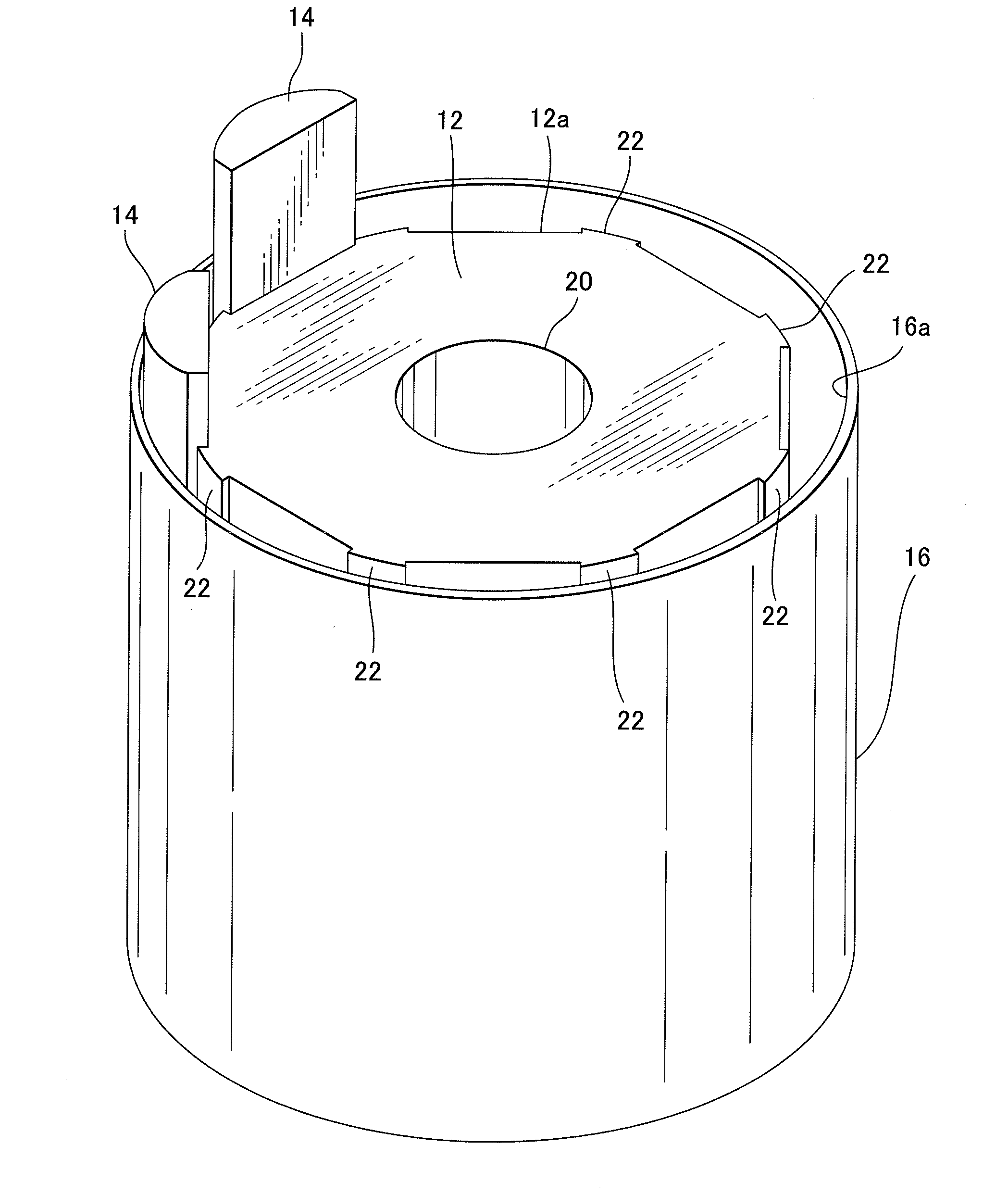
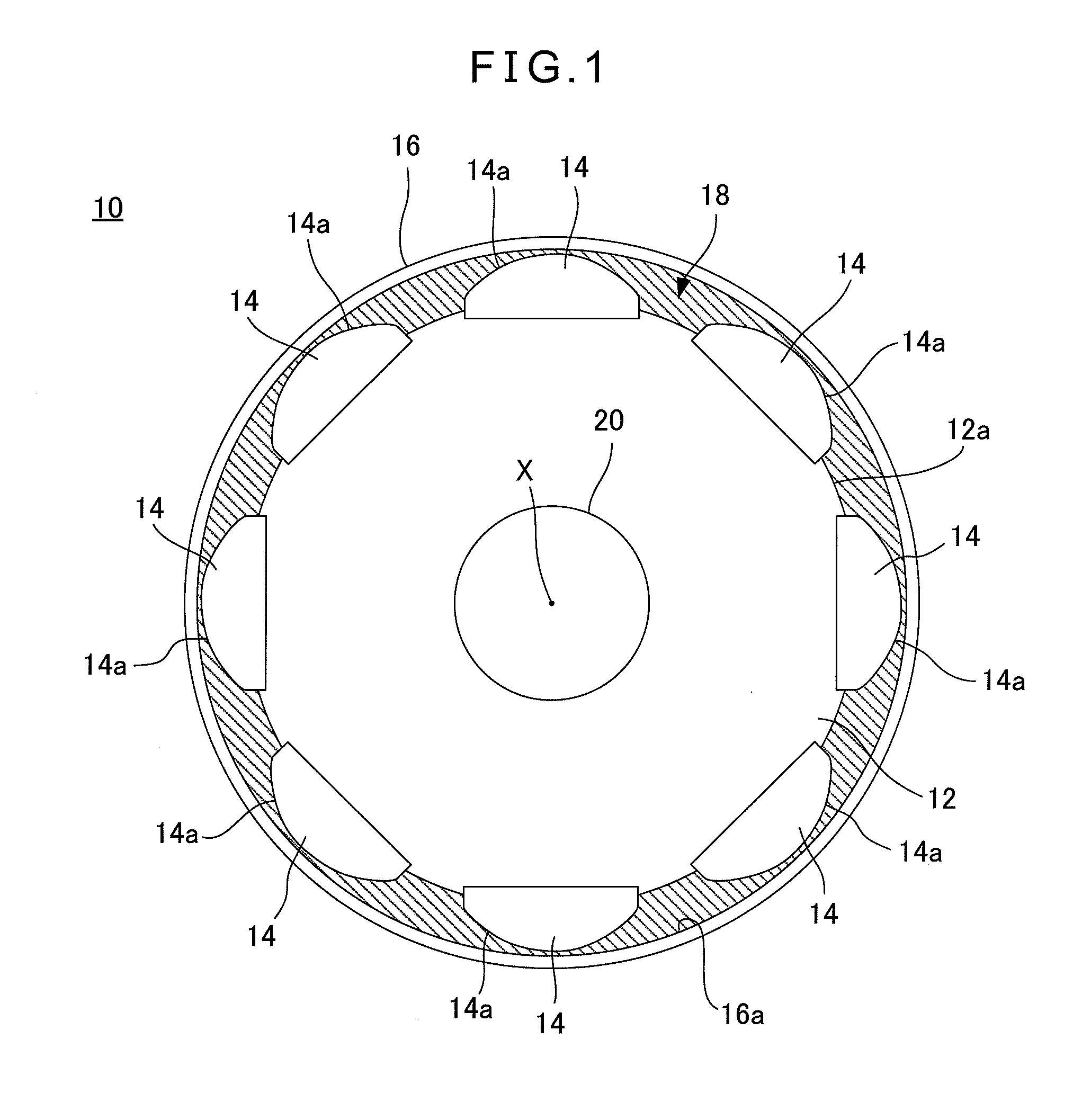
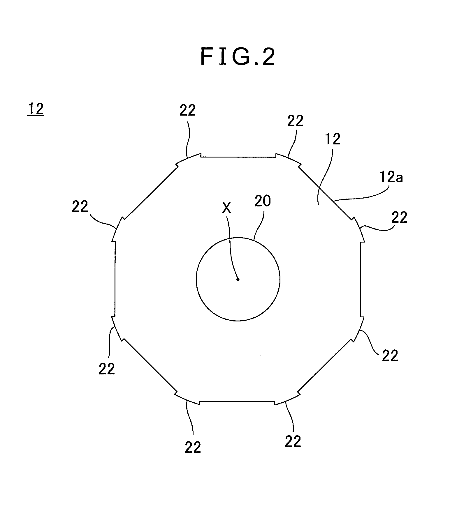
[0033]Embodiments of the present invention will be described below with reference to the accompanying drawings. In the illustrated embodiments, each element may be modified in size from the practical application for better understanding. FIG. 1 is a sectional view schematically showing a rotor 10 of an electric motor according to an embodiment of the present invention. FIG. 2 is a sectional view showing only a rotor core 12 in the embodiment of FIG. 1. FIG. 3 is a sectional view showing the rotor core 12 with magnets 14 attached thereto in the embodiment of FIG. 1.

[0034]The rotor 10 is a constituent element of an electric motor that is driven rotationally due to a magnetic action in cooperation with a stator (see FIG. 8). The rotor 10 includes a rotor core 12, a plurality of magnets 14 spaced apart from each other on an outer circumferential surface 12a of the rotor core 12, and a cylindrical protective pipe 16 provided so as to surround the plurality of magnets 14. A space defined ...


PUM

PropertyMeasurementUnit
Diameteraaaaaaaaaa
Magnetismaaaaaaaaaa
Ductilityaaaaaaaaaa

Abstract

In accordance with the present invention, a rotor of an electric motor including a rotor core, a plurality of magnets spaced apart from each other on an outer circumferential surface of the rotor core, and a cylindrical protective pipe surrounding the magnets is provided. The protective pipe has an inner diameter smaller than a diameter of a circumscribed circle passing through tops of outer surfaces of the magnets. A space defined by an inner surface of the protective pipe, the outer surfaces of the magnets and the outer surface of the rotor core is filled with resin, and the protective pipe is held so as to have a diameter larger than that of the circumscribed circle, due to injection pressure of the resin.

Description

BACKGROUND OF THE INVENTION[0001]1. Field of the Invention[0002]The present invention relates to a rotor of an electric motor having a structure for attaching magnets securely to a circumferential surface of an iron core, and to a manufacturing method thereof.[0003]2. Description of the Related Art[0004]In a rotor of an electric motor in which magnets are arranged on an outer circumferential surface of an iron core, adhesive is used in order to attach the magnets to the core. However, if adhesive is used, the amount and hardening of the adhesive have to be managed, so that cost tends to increase and quality control will be difficult. Further, not only is a cleaning step required to clean the surface of the core before adhesive is applied thereto, but an additional step is required to remove excess adhesive after the adhesive is applied. Moreover, magnets attached by means of adhesive make it difficult to ensure that the fixing structure has enough strength to withstand torque and ce...

Claims


Application Information

Patent Timeline
IPC IPC(8): H02K1/28H02K15/02H02K1/27
CPCH02K1/278H02K1/28Y10T29/49012H02K15/03H02K21/14H02K15/02
Inventor KOBAYASHI, KOUJITAMAKI, TAKESHI
Owner FANUC LTD
Why Eureka
Try Eureka