Polishing pad and method for producing same

a technology of polishing pad and surface, which is applied in the field of polishing pad, can solve the problems of uneven surface area of polishing pad, decreased polishing speed, and scratching (flaws) on the surface, and achieve the effect of improving the dressing property

Active Publication Date: 2013-08-22
ROHM & HAAS ELECTRONICS MATERIALS CMP HLDG INC
View PDF6 Cites 0 Cited by
  • Summary
  • Abstract
  • Description
  • Claims
  • Application Information

AI Technical Summary

Benefits of technology

[0010]An objective of the present invention is to provide a polishing pad that hardly causes scratches on t...

Problems solved by technology
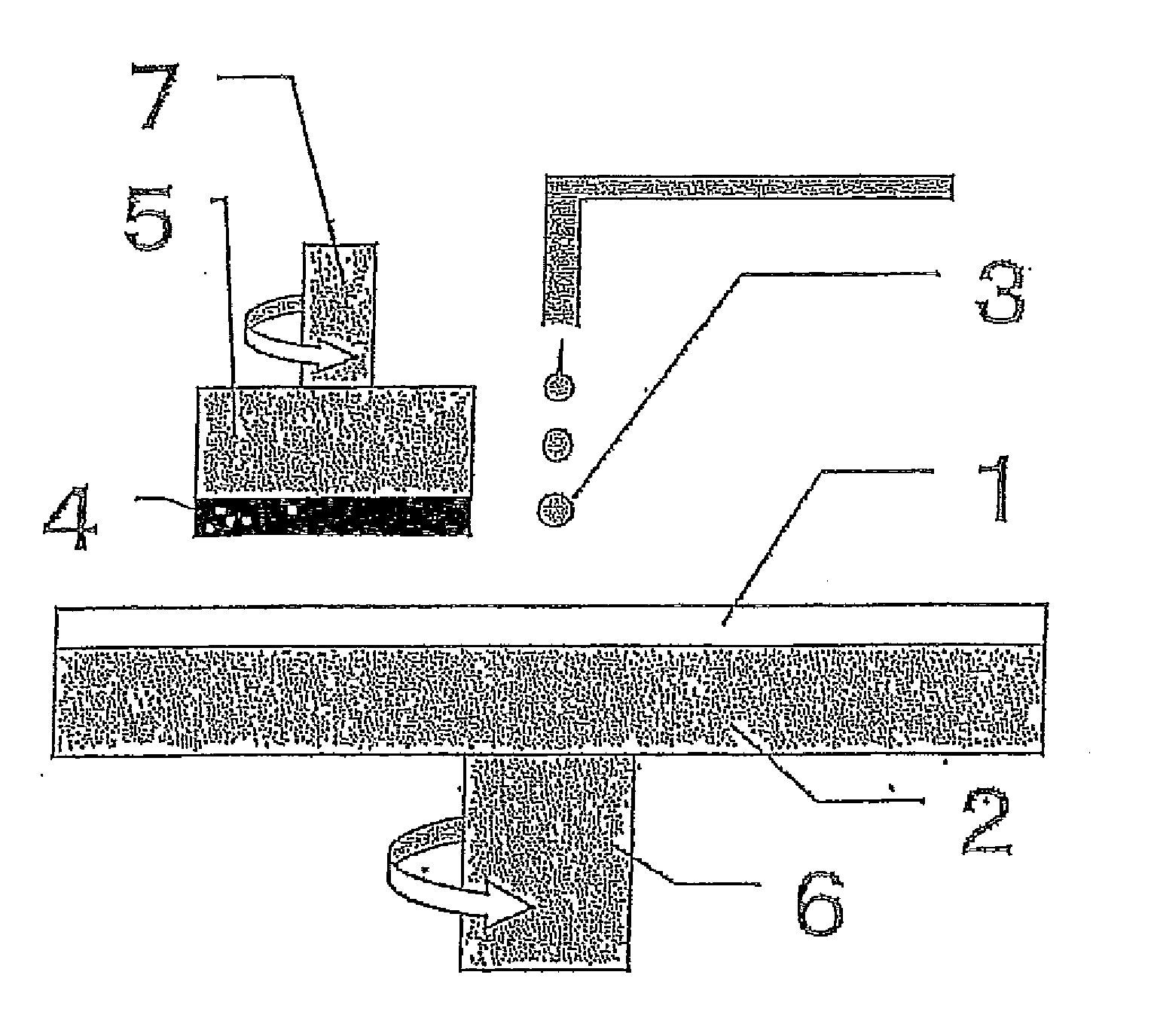
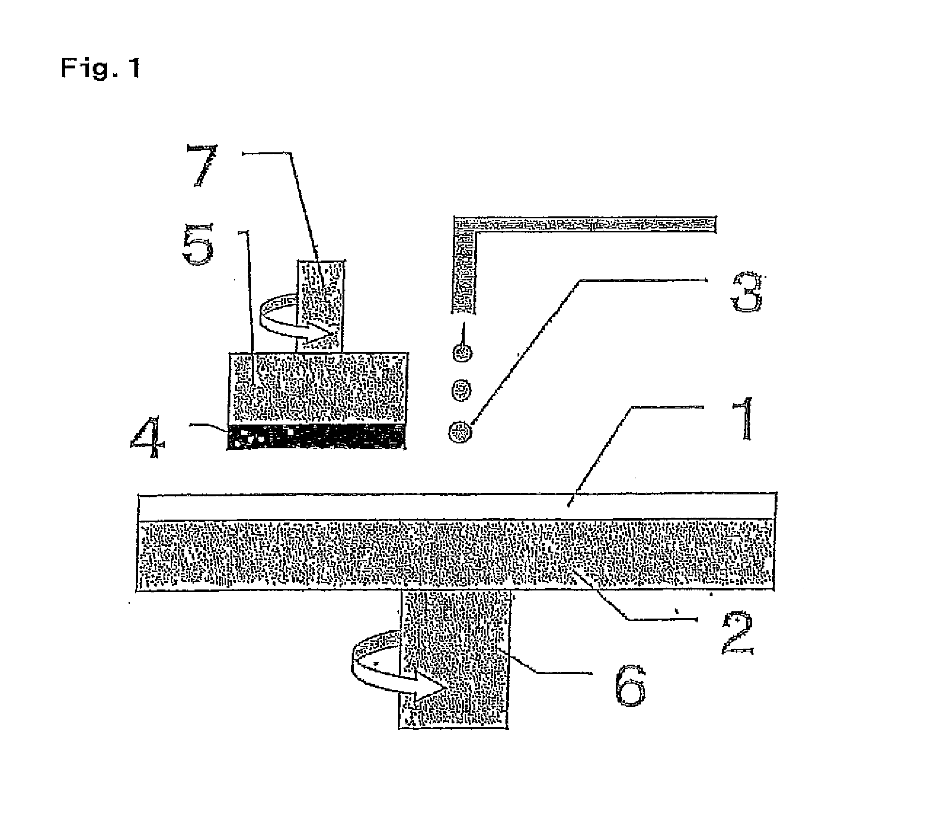
However, when a polishing pad comprising a foam is used, there is a problem such that scratches (flaws) are likely to occur on the surface to be polished of an object to be polished because the contact area between the object to be polished and the polishing pad becomes smaller and local surface pressure becomes higher.
On the other hand, when planarization process of a large number of semiconductor wafers is performed using a polishing pad, a fine uneven portion of the surface of the polishing pad is worn to deter...

Method used


Image

  • Polishing pad and method for producing same
  • Polishing pad and method for producing same
  • Polishing pad and method for producing same

Examples


example 1

[0081]To a vessel were added 1229 parts by weight of toluene diisocyanate (a mixture of toluene 2,4-diisocyanate / toluene 2,6-diisocyanate=80 / 20), 272 parts by weight of 4,4′-dicyclohexylmethane diisocyanate, 1901 parts by weight of polytetramethylene ether glycol with a number average molecular weight of 1018, and 198 parts by weight of diethylene glycol, and the mixture was allowed to react at 70° C. for 4 hours to obtain an isocyanate-terminated prepolymer A.

[0082]In addition, to a vessel were added 100 parts by weight of a polymerized 1,6-hexamethylene diisocyanate (Sumijule N-3300 (isocyanurate type) manufactured by Sumika Bayer Urethane Co., Ltd.) as an isocyanate-modified body and 16.3 parts by weight of polytetramethylene ether glycol with a number average molecular weight of 250 (NCO index: 4.0), and the mixture was allowed to react at 100° C. for 3 hours to obtain an isocyanate-terminated prepolymer B(1).

[0083]One hundred parts by weight of the prepolymer A and 16 parts by ...

example 2

[0084]A polishing pad was prepared in the same manner as in Example 1, except that in Example 1, the addition amount of the prepolymer B(1) was changed to 8 parts by weight from 16 parts by weight, and the addition amount of 4,4′-methylenebis(o-chloroaniline) was changed to 29.8 parts by weight from 33.1 parts by weight.

example 3

[0085]To a vessel were added 100 parts by weight of a polymerized 1,6-hexamethylene diisocyanate (Sumijule N-3300 (isocyanurate type) manufactured by Sumika Bayer Urethane Co., Ltd.) as an isocyanate-modified body and 42.4 parts by weight of polytetramethylene ether glycol with a number average molecular weight of 650 (NCO index: 4.0), and the mixture was allowed to react at 100° C. for 3 hours to obtain an isocyanate-terminated prepolymer B(2).

[0086]A polishing pad was prepared in the same manner as in Example 1, except that in Example 1, 16 parts by weight of the prepolymer B(2) was used in place of 16 parts by weight of the prepolymer B(1), and addition amount of 4,4′-methylenebis(o-chloroaniline) was changed to 31.9 parts by weight from 33.1 parts by weight.


PUM

PropertyMeasurementUnit
Angleaaaaaaaaaa
Percent by massaaaaaaaaaa

Abstract

A polishing pad has a polishing layer including a non-foamed polyurethane, wherein the non-foamed polyurethane is a reaction cured body of a polyurethane raw material composition containing an isocyanate-terminated prepolymer obtained by reacting a prepolymer raw material composition containing a diisocyanate, a high-molecular-weight polyol and a low-molecular-weight polyol; an isocyanate modified body polymerized by adding three or more diisocyanates; and a chain extender, and the addition amount of the isocyanate-modified body is 5 to 30 parts by weight with respect to 100 parts by weight of the isocyanate-terminated prepolymer. The polishing pad hardly causes scratches on the surface of an object to be polished and has an improved dressing property.

Description

TECHNICAL FIELD[0001]The invention relates to a polishing pad capable of performing planarization of materials requiring a high surface planarity such as optical materials including a lens and a reflecting mirror, a silicon wafer, a glass substrate or an aluminum substrates for a hard disc and a product of general metal polishing with stability and a high polishing efficiency. A polishing pad of the invention is preferably employed, especially, in a planarization step of a silicon wafer or a device on which an oxide layer or a metal layer has been formed prior to further stacking an oxide layer or a metal layer thereon.BACKGROUND ART[0002]Typical materials requiring surface flatness at high level include a single-crystal silicon disk called a silicon wafer for producing semiconductor integrated circuits (IC, LSI). The surface of the silicon wafer should be flattened highly accurately in a process of producing IC. LSI etc., in order to provide reliable semiconductor connections for v...

Claims


Application Information

Patent Timeline
IPC IPC(8): B24B37/24H01L21/304
CPCH01L21/304B24B37/24B24B37/00B28D5/04
Inventor NAKAI, YOSHIYUKIOGAWA, KAZUYUKINAKAMURA, KENJI
Owner ROHM & HAAS ELECTRONICS MATERIALS CMP HLDG INC
Why Eureka
Try Eureka