
Composition for high performance glass, high performance glass fibers and articles therefrom

a technology of high-performance glass and high-performance glass fibers, which is applied in the field of composition of high-performance glass, high-performance glass fibers and articles therefrom, can solve the problems of reducing productivity, process interruption, and forming r-glass and s-glass fibers at a dramatically higher cost than e-glass fibers, and achieves reduced production costs, improved product quality, and reduced fiberizing temperature

Active Publication Date: 2013-08-22
OWENS CORNING INTELLECTUAL CAPITAL LLC
View PDF2 Cites 15 Cited by
  • Summary
  • Abstract
  • Description
  • Claims
  • Application Information

AI Technical Summary

Benefits of technology

The present invention provides glass fibers that can be melted in a refractory-lined melter because their melting and fiberizing temperatures are below the upper use temperatures of conventional refractories. The glass fibers also have corrosion-resistant properties. The glass composition has a lower fiberizing temperature, which allows for a higher throughput and reduces production costs. The glass fibers have a fiberizing temperature of less than about 2650° F., a ΔT of at least about 80° F., and a coefficient of thermal expansion (CTE) of about 2.28×10⁻⁶ in / in / °F. to about 2.77×10⁻⁶ in / in°F. The glass fibers made from the inventive composition have the same corrosion-resisting properties as E-glass and boron-free glass fibers.

Problems solved by technology

Fiberizing R-glass at the customary 1000 poise viscosity would likely result in glass devitrification, which causes process interruptions and reduced productivity.
Further, the costs of forming R-glass and S-glass fibers are dramatically higher than E-glass fibers due to the cost of producing these fibers in a platinum-lined melter.

Method used


Image

  • Composition for high performance glass, high performance glass fibers and articles therefrom
  • Composition for high performance glass, high performance glass fibers and articles therefrom
  • Composition for high performance glass, high performance glass fibers and articles therefrom

Examples


example 1

Glass Formation

[0035]The glasses in the examples set forth in Tables 2A-2P were melted in platinum crucibles or in a continuous platinum-lined melter for determining the mechanical and physical properties of the glass and fibers produced therefrom. The units of measurement for the physical properties are: Viscosity (° F.), Liquidus temperature (° F.) and ΔT (° F.). In some examples the glasses were fiberized and Strength (KPsi), Density (g / cc), Modulus (MPsi), Softening Point (° F.) and coefficient of thermal expansion (CTE) (in / in / (° F.)) were measured.

[0036]The fiberizing temperature was measured using a rotating spindle viscometer. The fiberizing viscosity is defined as 1000 Poise. The liquidus temperature was measured by placing a platinum container filled with glass in a thermal gradient furnace for 16 hours. The greatest temperature at which crystals were present was considered the liquidus temperature. The modulus was measured using the sonic technique on a single fiber of gl...

example 2

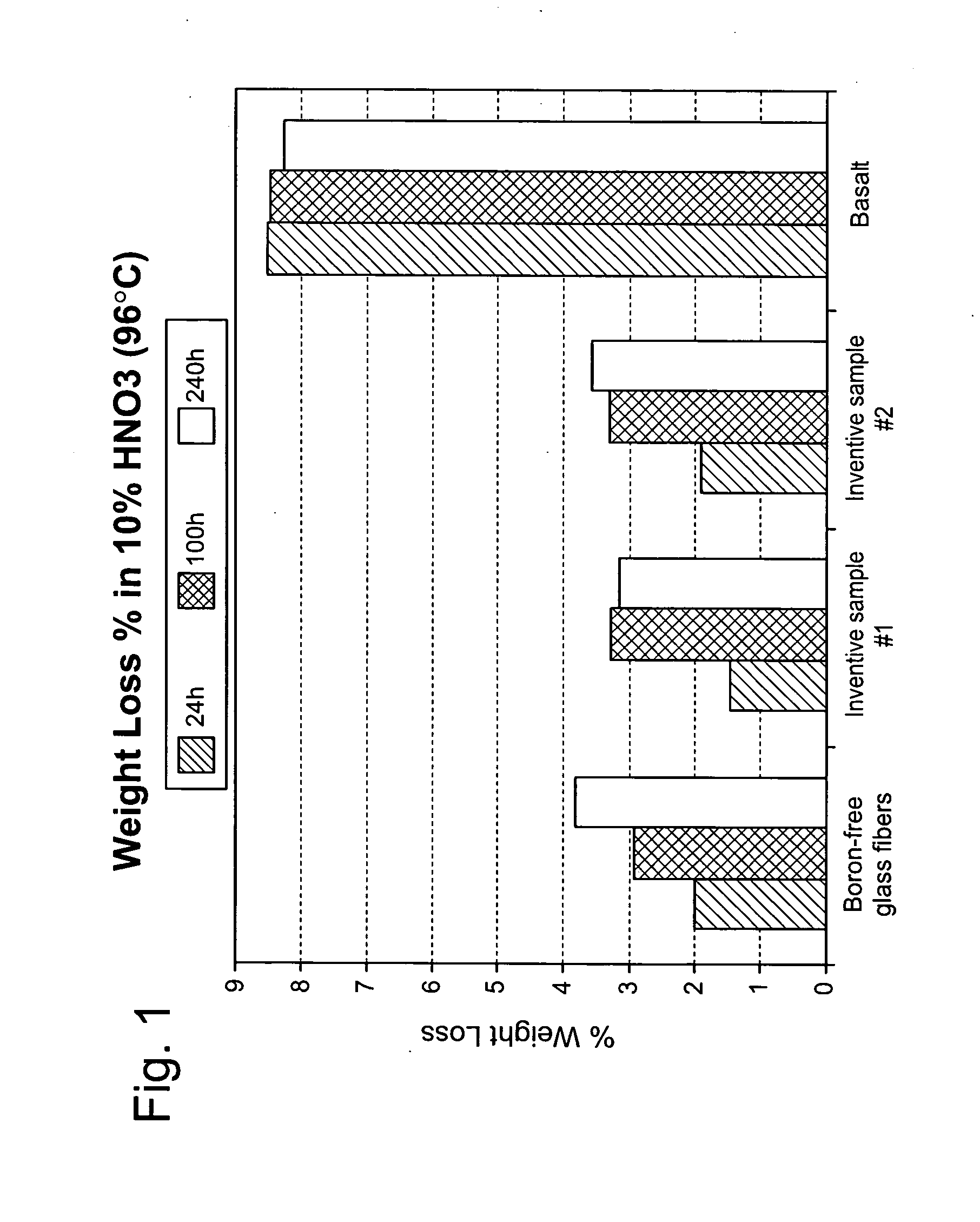
Corrosion Resistance of Glass Fibers Formed from the Inventive Composition in 10% HNO3

[0040]Samples from rovings of glass fibers formed in accordance with the inventive composition and a sample from a roving of boron-free fibers were desized by heating the fibers in a furnace at 625° C. for 30 minutes. The bare fibers were then permitted to cool in a dessicator. Once the fibers were cool, the samples were taken from the dessicator and each of the bare fiber samples were weighed (W1) and recorded. A sample of basalt was also obtained, weighed (W1), and recorded. The samples (i.e., inventive bare fibers, boron-free bare fibers, and basalt) were individually placed in flasks to which 150 ml of 10% HNO3 was added. The flasks were placed in a bath at 96° C. for 24 hours, 100 hours, and 240 hours. At the end of their respective time period, the samples of inventive fibers, boron-free fibers, and basalt were removed from the flasks and filtered through filter paper. The paper filters were...

example 3

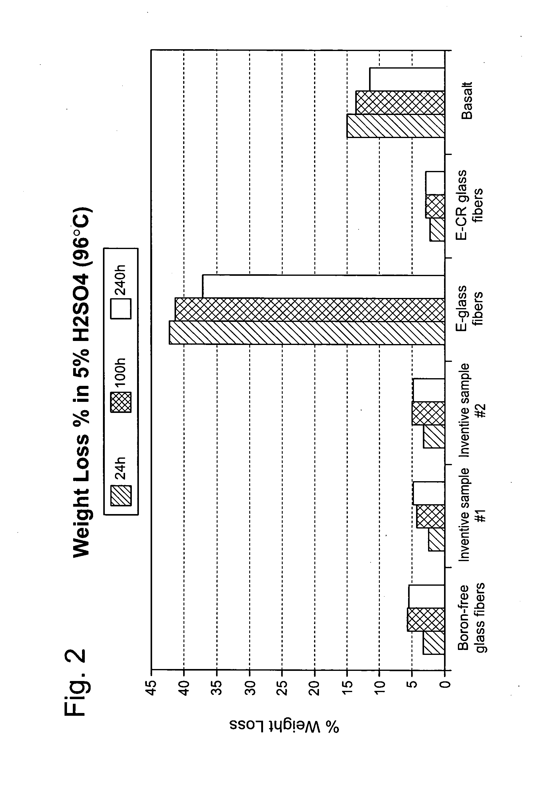
Corrosion Resistance of Glass Fibers Formed from the Inventive Composition in 5% H2SO4

[0042]Samples from rovings of glass fibers formed in accordance with the inventive composition, a sample from a roving of boron-free fibers, a sample from a roving of E-glass fibers, and a sample from a roving of E-CR glass were desized by heating the fibers in a furnace at 625° C. for 30 minutes. The bare fibers were then permitted to cool in a dessicator. Once the fibers were cool, the samples were taken from the dessicators and each of the bare fiber samples were weighed (W1) and recorded. A sample of basalt was also obtained, weighed (W1), and recorded. The samples (i.e., inventive bare fibers, boron-free bare fibers, E-glass bare fibers, E-CR bare fibers, and basalt) were individually placed in flasks and 150 ml of 5% H2SO4 was added. The flasks were then placed in a bath at 96° C. for 24 hours, 100 hours, and 240 hours. At the end of their respective time period, the samples of inventive fib...


PUM

PropertyMeasurementUnit
fiberizing temperatureaaaaaaaaaa
weight percentaaaaaaaaaa

Abstract

Glass batch compositions for the formation of high-modulus, and high-strength glass fibers as well as fibers suitable for use as textile and reinforcements are disclosed. Fibers formed of the composition are especially suitable for use in high-strength, low-weight applications such as windmill blades and high strength and modulus applications where strength and stiffness are required in the composite. The glass composition is up to about 70.5 weight % SiO2, about 24.5 weight % Al2O3, about 22 weight % alkaline earth oxides and may include small amounts of alkali metal oxides and ZrO2. Additionally, glass fibers formed from the inventive composition are non-corrosive or substantially non-corrosive in nature. Due to the non-corrosive nature of the glass fibers, glass fibers made with the inventive composition may be used in applications where the glass fibers or a composite formed from the glass fibers are in contact with a corrosive substance.

Description

CROSS REFERENCE TO RELATED APPLICATIONS[0001]This application is a continuation-in-part of U.S. patent application Ser. No. 11 / 267,739 entitled “Composition For High Performance Glass, High Performance Glass Fibers, and Articles Therefrom” filed Nov. 4, 2005, the content of which is incorporated by reference in its entirety.TECHNICAL FIELD AND INDUSTRIAL APPLICABILITY OF THE INVENTION[0002]The present invention relates generally to a composition for continuous glass fibers, and more particularly to a glass composition for use in high-strength applications as well as high-strength glass fibers and articles that have non-corrosive properties.BACKGROUND OF THE INVENTION[0003]Fiberglass is manufactured from various raw materials combined in specific proportions to yield a desired chemical composition. This proportion is commonly termed a “glass batch.” The composition of the glass batch and the glass manufactured from it are typically expressed in terms of percentages of the components,...

Claims


Application Information

Patent Timeline
Patent Type & Authority Applications(United States)
IPC IPC(8): C03C13/00C08K7/14
CPCC03C13/00C03C3/087C08K7/14C03C3/112C03C13/06
Inventor HOFMANN, DOUGLAS A.MC GINNIS, PETER B.
Owner OWENS CORNING INTELLECTUAL CAPITAL LLC
Learn More