Method for directory entries split and merge in distributed file system

a file system and directory entry technology, applied in the field of storage systems, can solve the problems of difficult to determine to which metadata server a directory entry should be created, the extension of this method to a distributed storage environment, and the inability to create directory entries, so as to minimize the impact of file creation performance and improve the performance of file creation

Inactive Publication Date: 2013-08-22
HITACHI LTD
View PDF6 Cites 68 Cited by
  • Summary
  • Abstract
  • Description
  • Claims
  • Application Information

AI Technical Summary

Benefits of technology

[0006]Exemplary embodiments of the invention provide a method for distributing directory entries to multiple metadata servers to improve the performance of file creation under a single directory, in a distributed system environment. The method disclosed in U.S. Pat. No. 5,893,086 is limited to a shared disk environment. Extension of this method to a distributed storage environment, where each metadata server has its own storage, is unknown and nontrivial. Firstly, as the hash tree is not explicitly maintained for a directory, it is difficult to determine to which metadata server a directory entry should be created. Secondly, when a directory entry is migrated from one metadata server to another, the corresponding file should be migrated as well to retain namespace consistency in both metadata servers. Efficient file migration method is needed to minimize the impact to file creation performance for user applications. Lastly, it is more desired that the number of metadata servers to which directory entries are distributed can be dynamically changed based on file creation rate instead of file number.

Problems solved by technology

Extension of this method to a distributed storage environment, where each metadata server has its own storage, is unknown and nontrivial.
Firstly, as the hash tree is not explicitly maintained for a directory, it is difficult to determine to which metadata server a directory entry should be created.

Method used


Image

  • Method for directory entries split and merge in distributed file system
  • Method for directory entries split and merge in distributed file system
  • Method for directory entries split and merge in distributed file system

Examples


embodiment 1

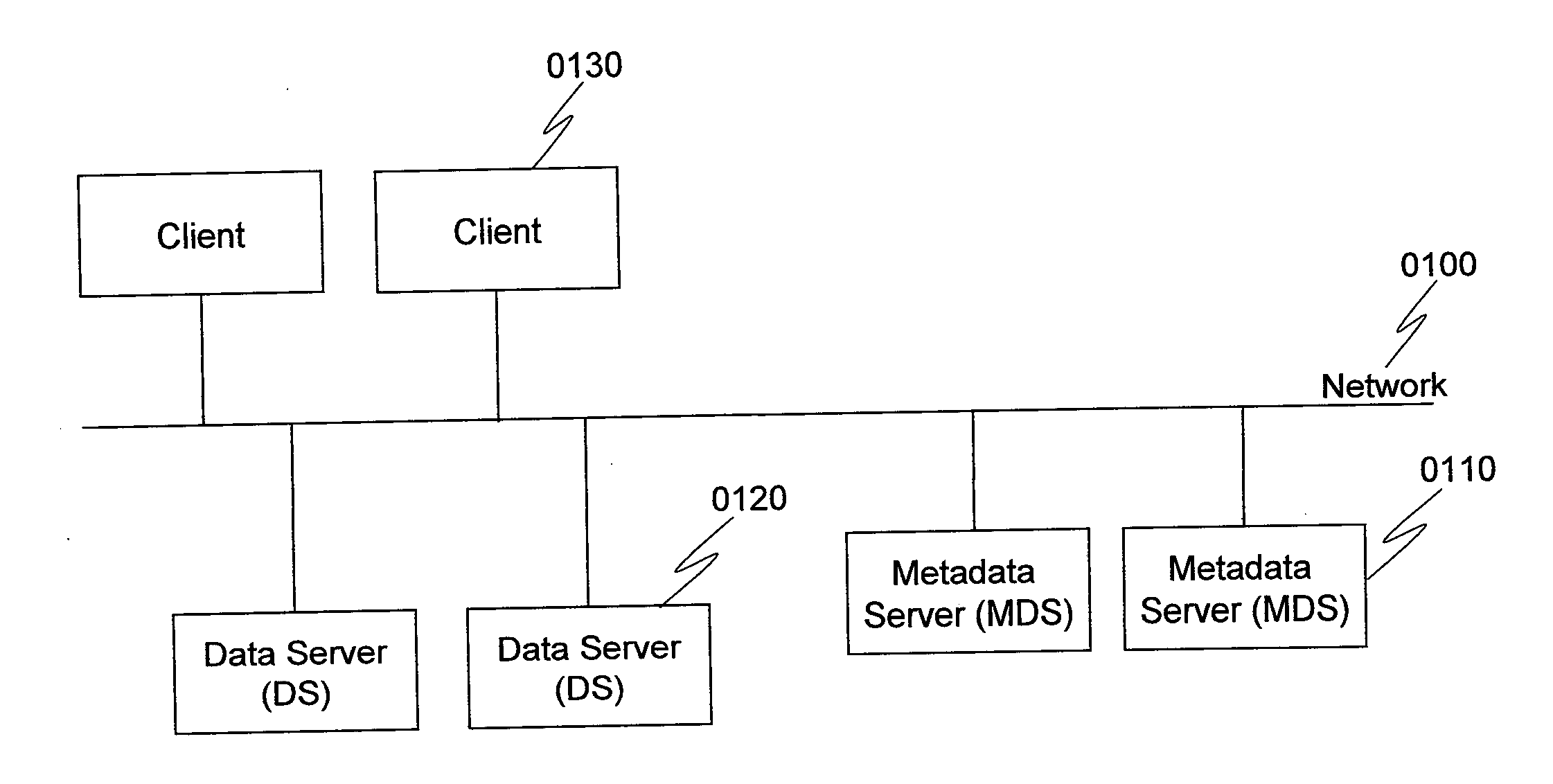
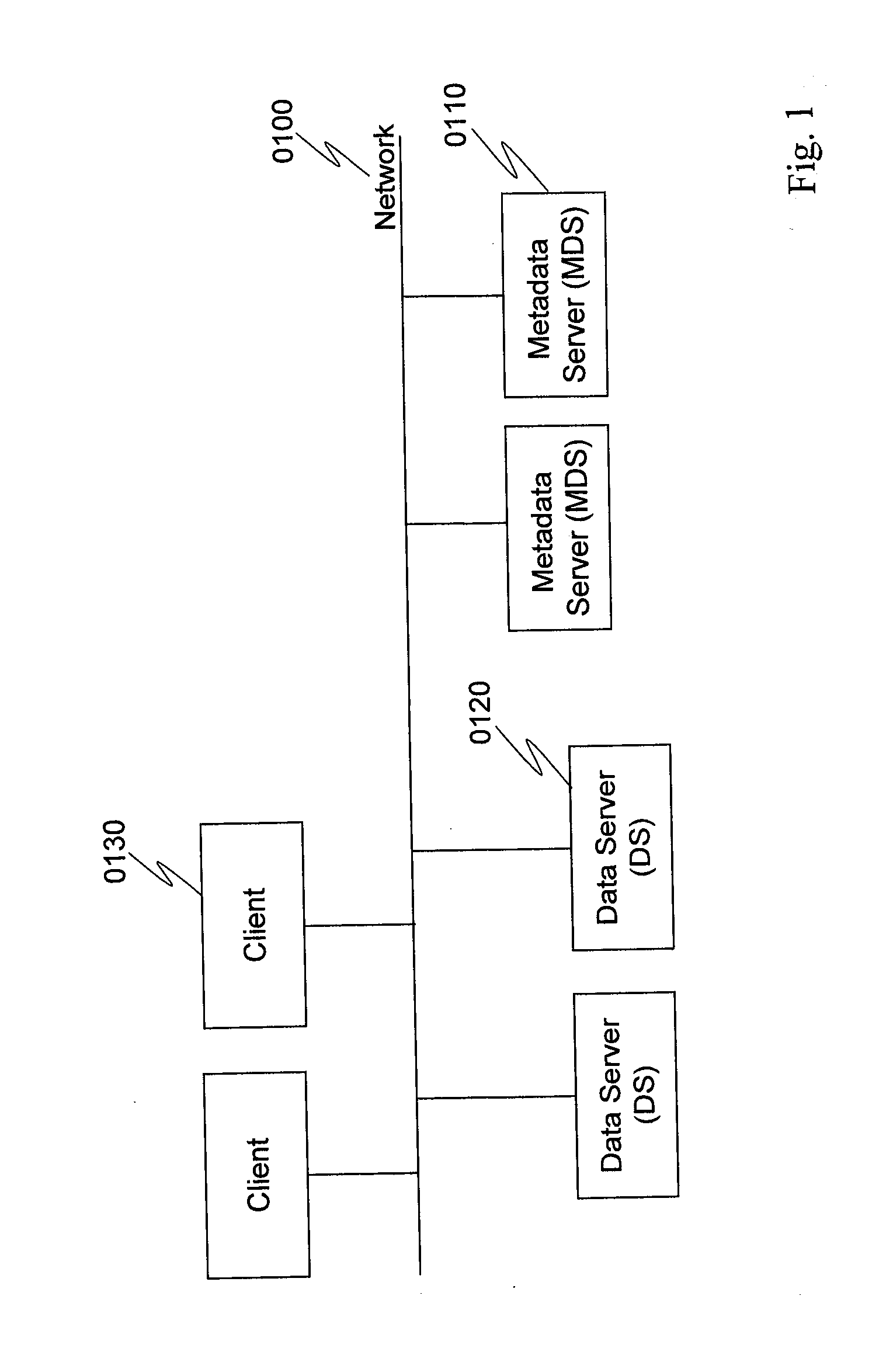
[0052]FIG. 1 is an exemplary diagram of an overall system according to a first embodiment of the present invention. The system includes a plurality of Metadata Servers (MDSs) 0110, Data Servers (DSs) 0120, and Clients 0130 connected to a network 0100 (such as a local area network). MDSs 0110 are the metadata servers where the file system metadata (e.g., directories and location information of file contents) are stored. Data servers 0120 are the devices, such as conventional NAS (network attached storage) devices, where file contents are stored. Clients 0130 are devices (such as PCs) that access the metadata from MDSs 0110 and the file contents from DSs 0120.

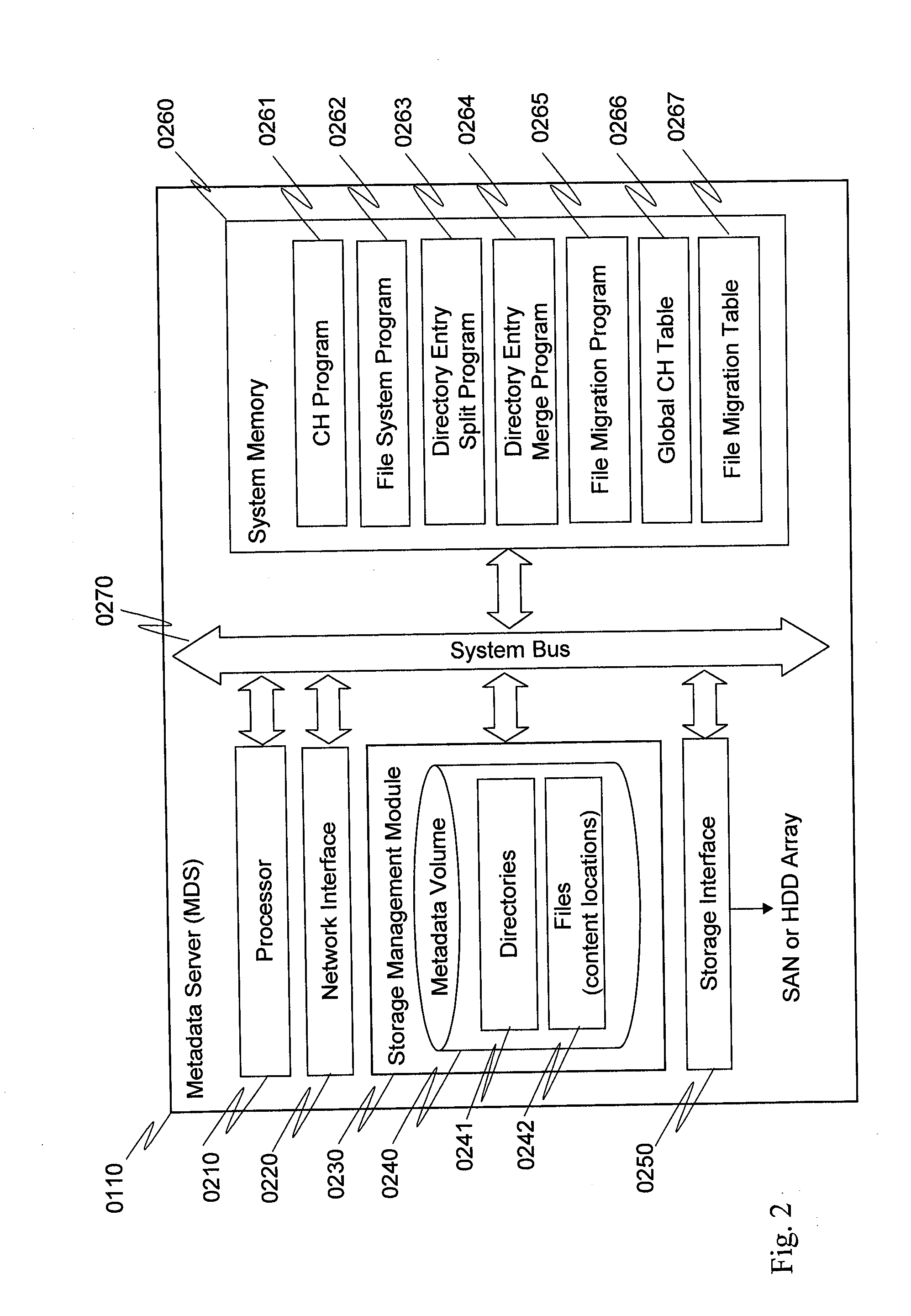
[0053]FIG. 2 is a block diagram illustrating the components within a MDS 0110. The MDS may include, but is not limited to, a processor 0210, a network interface 0220, a storage management module 0230, a storage interface 0250, a system memory 0260, and a system bus 0270. The system memory 0260 includes a CH (consistent hashing) p...

embodiment 2

[0079]A second embodiment of the present invention will be described next. The explanation will mainly focus on the differences from the first embodiment. In the first embodiment, to split directory entries, the master MDS of the directory assigns IDs to the slave MDSs in the way that each MDS in the local CH table 0850 manages an equivalent ID range (see Step 1330 of FIG. 13). Similarly, to add a new slave MDS to the local CH table 0850, the master MDS assigns an ID to the new slave MDS so that both the new slave MDS and its successor MDS manage an equivalent ID range (Step 1805 of FIG. 18). The aforementioned ID assignment does not consider the capability of each MDS (in terms of CPU power, disk IO throughput, or the combination), and may cause workload imbalance to the MDSs in the local CH table 0850. Therefore, in the second embodiment, the master MDS assigns an ID to a slave MDS based on the capability of the slave MDS.

[0080]To this end, for a local CH table 0850, a quota colum...

embodiment 3

[0083]A third embodiment of the present invention will be described in the following. The explanation will mainly focus on the differences from the first and second embodiments. In the first and second embodiments, a global CH table 0266 which consists of all the MDSs 0110 in the system is maintained by each MDS. A client 0130 has no hashing capability and does not maintain the global CH table. As the clients have no knowledge on where a directory is stored, the clients may send a directory access request to a MDS 0110 where the directory is not stored, incurring additional communication cost between the MDSs. In the third embodiment, a client can execute the same hash function as in the CH program 0261 and maintain the global CH table 0266. A client can then send a directory access request directly to the master MDS of the directory by looking up the global CH table 0266, so that communication cost between MDSs can be reduced.


PUM


Abstract

A distributed storage system has MDSs (metadata servers). Directories of file system namespace are distributed to the MDSs based on hash value of inode number of each directory. Each directory is managed by a master MDS. When a directory grows with a file creation rate greater than a preset split threshold, the master MDS constructs a consistent hashing overlay with one or more slave MDSs and splits directory entries of the directory to the consistent hashing overlay based on hash values of file names under the directory. The number of MDSs in the consistent hashing overlay is calculated based on the file creation rate. When the directory continues growing with a file creation rate that is greater than the preset split threshold, the master MDS adds a slave MDS into the consistent hashing overlay and splits directory entries to the consistent hashing overlay based on hash values of file names.

Description

BACKGROUND OF THE INVENTION[0001]The present invention relates generally to storage systems and, more particularly to a method for distributing directory entries to multiple metadata servers in a distributed system environment.[0002]Recently technologies in distributed file system, such as parallel network file system (pNFS) and the like, enable an asymmetric system architecture, which consists of a plurality of data servers and metadata servers. In such a system, file contents are typically stored in the data servers, and metadata (e.g., file system namespace tree structure and location information of file contents) are stored in the metadata servers. Clients first consult the metadata servers for the location information of file contents, and then access file contents directly from the data servers. By separating the metadata access from the data access, the system is able to provide very high IO throughput to the clients. One of the major use cases for such a system is high perfo...

Claims


Application Information

Patent Timeline
Patent Type & Authority Applications(United States)
IPC IPC(8): G06F17/30
CPCG06F17/30194G06F16/182
Inventor LIN, WUJUANSHIGA, KENTA
Owner HITACHI LTD
Why Eureka
Try Eureka