Transmitter Linearized Using Look-Up Table With Unadaptable Data and Method Therefor

a linearized, unadaptable technology, applied in the field of predistorters, can solve the problems of transmitters that cannot be successfully operated transmitters that cannot be reliably synchronized with the baseband system, and may fail to achieve the effect of successfully operating within the spectral mask imposed by regulations and/or power specifications,

Inactive Publication Date: 2013-08-29
CRESTCOM INC
View PDF0 Cites 30 Cited by
  • Summary
  • Abstract
  • Description
  • Claims
  • Application Information

AI Technical Summary

Problems solved by technology

To the extent that the amplifier is imperfectly linear, distortion and spectral regrowth result.
If this distortion and spectral regrowth are excessive, then the transmitter may fail to successfully operate within a spectral mask imposed by regulations and/or within power specifications.
Non-linearity in an amplifier causes the generation of signal harmonics as a unwanted byproduct of amplification.
This envelope-induced video signal modulates amplifier gain causing further deterioration in amplifier linearity.
They represent another form of video signal that can further modulate amplifier gain, causing still further deterioration in amplifier linearity.
But the video signal is not eliminated, so the distortion it causes remains to some extent.
When impedance in the fundamental RF band is insufficiently high, amplifier efficiency suffers.
Furthermore, several different physical characteristics of an amplifier cause different nonlinearities, with the video-signal-induced nonlinearity being only one.
The difficulty associated with linearizing memory effects may result from the fact that conventional amplifiers appear to exhibit many different and distinct long term and short term memory effects cross correlated with one another but each having its own unique spectral characteristics and each contributing a different degree of distortion.
Unfortunately, due to numerous unknown terms, a considerable amount of cross correlation between the terms, and a large span of time over which different memory effects play ou

Method used


Image

  • Transmitter Linearized Using Look-Up Table With Unadaptable Data and Method Therefor
  • Transmitter Linearized Using Look-Up Table With Unadaptable Data and Method Therefor
  • Transmitter Linearized Using Look-Up Table With Unadaptable Data and Method Therefor

Examples


first embodiment

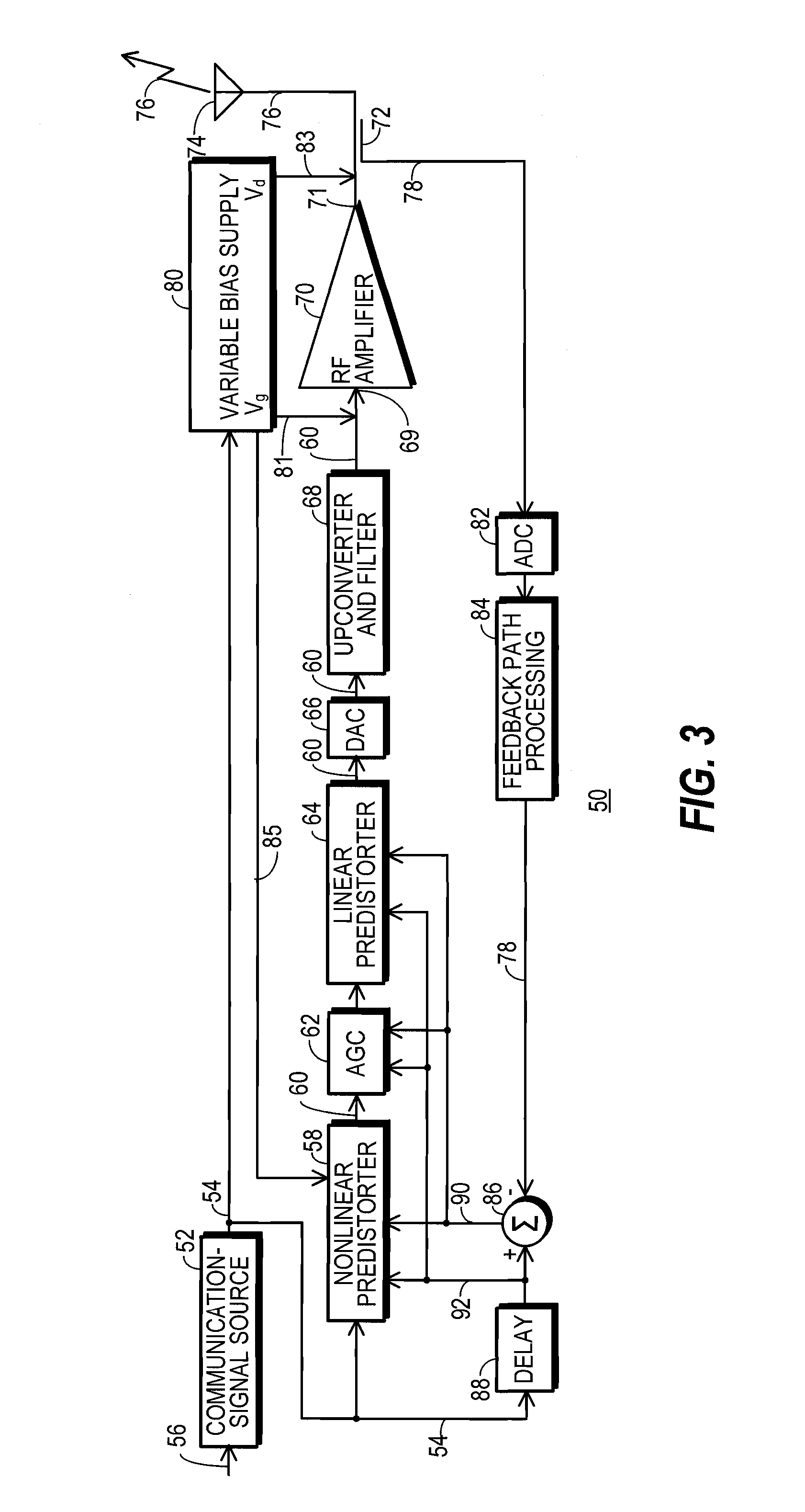
[0059]FIG. 4 shows a simplified block diagram of transmitter 50 as discussed above and as shown in FIG. 3, but with details concerning nonlinear predistorter 58 shown, with details of a behavioral model 94 for amplifier 70 shown, and with other details omitted.

[0060]The block diagram of model 94 presented in FIG. 4 provides an explanation for the way in which linear and nonlinear influences associated with amplifier 70 appear to behave. Those skilled in the art will appreciate that amplifier 70 is constructed from real components and materials that fail to operate precisely as desired. Accordingly, models, such as model 94, may be devised to explain the manner in which amplifier 70 appears to actually operate. The specific components of model 94 need not be individually observable in a real-world version of amplifier 70.

[0061]Model 94 depicts amplifier 70 as having its overall transfer function partitioned into a linear component 96 and a nonlinear component, referred to herein as a...

second embodiment

[0140]FIG. 11 shows joining and gain-adjusting section 162 of the nonlinear predistorter 58. The FIG. 11 embodiment represents a simplification over the FIG. 10 embodiment, and it requires fewer complex multiply operations and consumes correspondingly less power. The FIG. 11 embodiment is suitable for use when processing section 156 (FIGS. 4 and 9) configures transform FML2 with FML1−1 to provide a better estimate of the combined inverse of FML1 in parallel with FML2 than is provided by FML1−1 alone. In this embodiment, alternate error signal 90′ is supplied to derivative neutralizer 220 (FIG. 9).

[0141]In this FIG. 11 embodiment, gain-correcting signal 160 generated through the application of transform FML2 is viewed as an offset to gain-correcting signal 158, which is generated through the application of transform FML1−1. But nothing requires FML1−1 for this embodiment to precisely equal FML1−1 for the other embodiment or to precisely equal the inverse of gain-droop component 146 c...

fourth embodiment

[0160]FIG. 15 shows a block diagram of predistorter 58. In the FIG. 15 embodiment the above-discussed parameters that drive or may drive address inputs to adaptable LUT 282 have been combined to reduce the size of LUT 282. As in FIG. 13, FIG. 15 drops the complex signal notation used above in FIGS. 8-11.

[0161]The FIG. 13 embodiment of predistorter 58 uses up to five different, albeit related, parameters to independently drive up to five different address inputs of LUT 282, where each of the five different address inputs may include one or more address bits. The five different parameters may be grouped into two different groups. Each parameter in one group of parameters is proportional to different modulations of Vgs (FIG. 14). This group of parameters includes magnitude parameter 152 and variable gate bias parameter 81′. Each parameter in another group of parameters is proportional to different modulations of Vds (FIG. 14). This group of parameters includes magnitude derivative para...


PUM


Abstract

A transmitter (50) includes a low power nonlinear predistorter (58) that inserts predistortion configured to compensate for a memoryless nonlinearity (146) corresponding to gain droop and another memoryless nonlinearity (148) corresponding to a video signal. When efforts are taken to reduce memory effects, such as configuring a network of components (138) that couple to an HPA (114) to avoid resonance frequencies within a video bandwidth (140), high performance linearization at low power results without extending linearization beyond that provided by the memoryless nonlinear predistorter (58). A unadaptable look-up table (370) has address inputs responsive to a magnitude parameter (152) of a communication signal (54), a magnitude derivative parameter (204) of the communication signal (54), and a parameter (346, 366) related either directly or indirectly to battery voltage. The unadaptable look-up table (370) produces a gain-correcting signal (284) that adjusts the gain applied to the communication signal (54) prior to amplification.

Description

TECHNICAL FIELD OF THE INVENTION[0001]The present invention relates generally to the field of communication systems. Specifically, the present invention relates to predistorters which reduce distortion introduced into a communication signal by an imperfectly linear amplifier.BACKGROUND OF THE INVENTION[0002]Many popular modulation formats used in the field of digital communications assume the availability of a linear amplifier in a transmitter to boost a communication signal to a level at which it may be successfully broadcast from an antenna, then propagate to and be demodulated by a remotely located receiver. Linearity refers to the ability of an amplifier to faithfully reproduce a signal presented to it without causing the output signal from the amplifier to be distorted in some way. To the extent that the amplifier is imperfectly linear, distortion and spectral regrowth result. If this distortion and spectral regrowth are excessive, then the transmitter may fail to successfully ...

Claims


Application Information

Patent Timeline
IPC IPC(8): H04L25/49
CPCH04L25/03343H03G3/3042H03F1/3247H03F1/56H03F3/1935H03F3/245H03F2200/108H03F2200/15H03F2200/18H03F2200/204H03F2200/207H03F2200/336H03F2200/387H03F2200/465H03F2200/555H03F2201/3209H03F2201/3212H03F2201/3224H03F2201/3233H03F1/0266
Inventor MCCALLISTER, RONALD DUANE
Owner CRESTCOM INC
Why Eureka
Try Eureka