Determining changes in the x-ray emission yield of an x-ray source

Inactive Publication Date: 2013-08-29
KONINKLIJKE PHILIPS ELECTRONICS NV
View PDF9 Cites 42 Cited by
  • Summary
  • Abstract
  • Description
  • Claims
  • Application Information

AI Technical Summary

Benefits of technology

[0008]Such an X-ray source allows determining changes in the X-ray emission yield, because

Problems solved by technology

It has been shown that when the tube yield degrades, due to system limits, the X-ray dose emitting from the X-ray source can become too low.
Further, i

Method used


Image

  • Determining changes in the x-ray emission yield of an x-ray source
  • Determining changes in the x-ray emission yield of an x-ray source
  • Determining changes in the x-ray emission yield of an x-ray source

Examples


Embodiment Construction

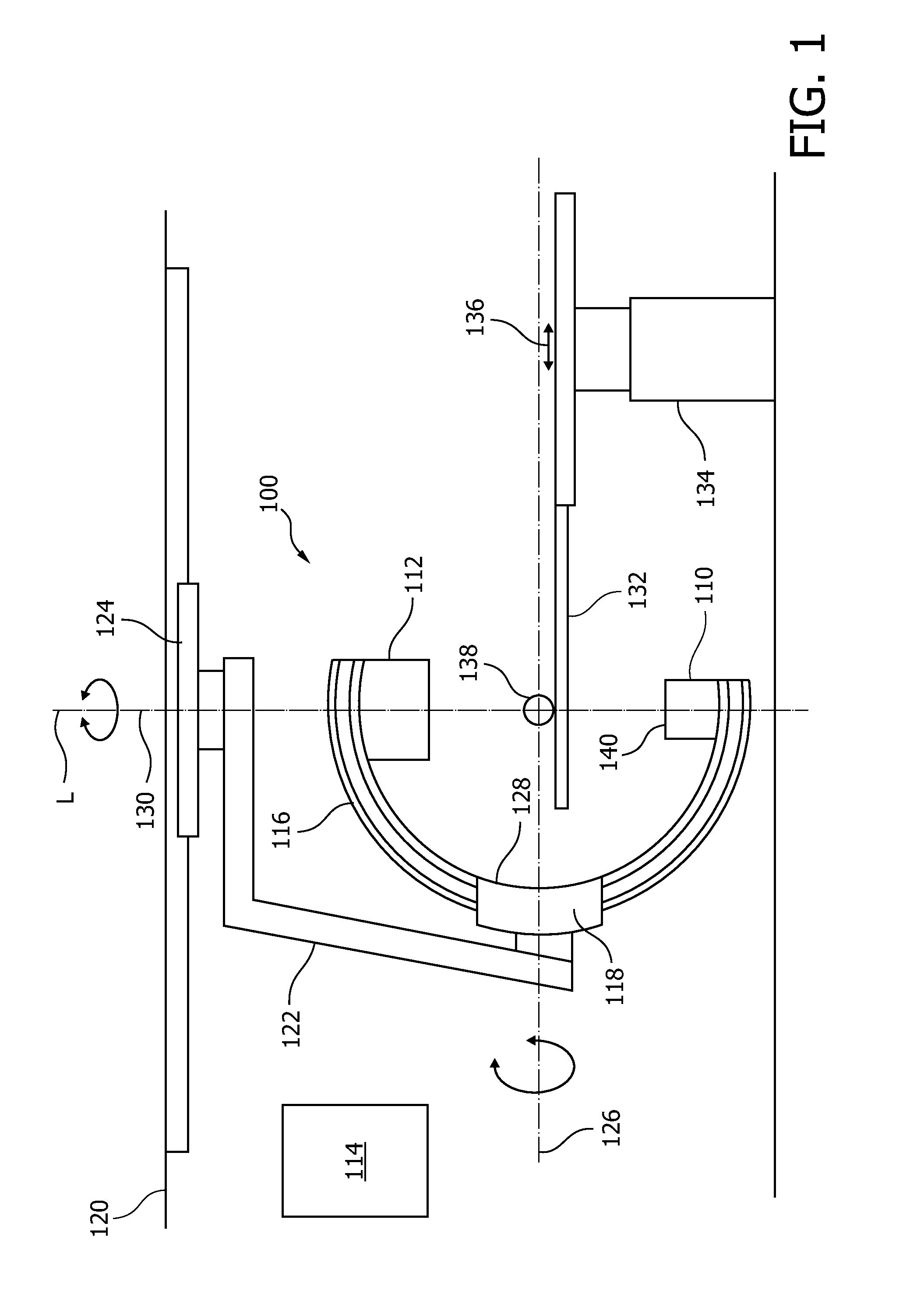
[0039]FIG. 1 schematically illustrates an X-ray imaging system 100 with an X-ray source 110, a detector 112, and a processing unit 114. The X-ray source 110 and the X-ray detector 112 are arranged on opposite ends of a C-arm 116. The C-arm 116 is rotatably supported by a C-arm support 118, which C-arm support 118 is suspended from a ceiling 120 by a rotatable support arm 122. The latter is mounted rotatably to the ceiling 120 by a ceiling mount 124. The C-arm 116 can be rotated around a horizontal axis, indicated with reference numeral 126. Further, the C-arm is slidably movable in a curve-like manner in a sliding support device 128 of the C-arm support 118. The support arm 122 can be rotated around a vertical axis, indicated with reference numeral 130. Thus, the detector 112 and the X-ray source 110 can be brought to a large number of positions with respect to an object to be investigated 138. Further, an object supporting device in form of a table 132 is provided, which table can ...


PUM


Abstract

The present invention relates to determining changes in the X-ray emission yield of an X-ray tube, in particular determining dose degradation. In order to provide determination of such changes, an X-ray source is provided comprising a cathode, an anode; and at least one X-ray sensor (16). The cathode emits electrons towards the anode and the anode comprises a target area on which the electrons impinge, generating X-ray radiation. An X-ray barrier (24) is provided with an aperture (26) for forming an emitting X-ray beam from the X-ray radiation, wherein the emitting X-ray beam has a beam formation (30) with a central axis. The at least one X-ray sensor is arranged within the beam formation and measures the X-ray intensity for a specific direction of X-ray emission with an angle with respect to the central axis. The at least one X- ray sensor can be positioned inside the beam formation (30), but outside the “actual field of view” (40) as determined by a diaphragm (36).

Description

FIELD OF THE INVENTION[0001]The present invention relates to determining changes in the X-ray emission yield of an X-ray tube, in particular to determining dose degradation. The invention relates in particular to an X-ray source, an X-ray imaging system, a method for determining changes in the X-ray emission yield of an X-ray source, a computer program element, and a computer-readable medium.BACKGROUND OF THE INVENTION[0002]In X-ray sources, for example in X-ray tubes, electrons with kilovolt energies impact onto the focal track of an anode, for example a rotating anode, for generating X-ray radiation. This leads among others to modifications of the anode surface. As a consequence, the tube X-ray yield changes over the course of its lifetime, which may have an impact on the X-ray application. In US 2009 / 0067578 A1, a rotatable anode is described with a structure comprising slits, for example, which structure can be detected if the structure on the anode passes the focal spot. Thus, ...

Claims


Application Information

Patent Timeline
IPC IPC(8): H05G1/54
CPCH01J35/02A61B6/507H05G1/54H05G1/30
Inventor SPRONG, HANS PETERSPRONG, MARTIN KIMUTAIKIEWITT, RAINER
Owner KONINKLIJKE PHILIPS ELECTRONICS NV
Why Eureka
Try Eureka