External cavity laser array system and WDM optical system including same

a laser array and optical system technology, applied in the field of external cavity laser array systems, can solve the problems of inefficient tdm approach, complex and expensive cost of deployment and managing many fibers, and increase in fiber coun

Active Publication Date: 2013-08-29
APPLIED OPTOELECTRONICS
View PDF4 Cites 51 Cited by
  • Summary
  • Abstract
  • Description
  • Claims
  • Application Information

AI Technical Summary

Problems solved by technology

As the number of subscribers connected to the network increases, the fiber count also increases rapidly and the expense of deploying and managing many fibers becomes complex and expensive.
Each subscriber may be connected to the network utilizing a much shorter fiber span forming an architecture sometimes referred to as “tree and branch.” One challenge in developing such a PON is utilizing the capacity in the trunk fiber efficiently in order to transmit the maximum possible amount of information on the trunk fiber.
Although TDM-PON systems work, the TDM approach is inefficient because the system should allow sufficient time between different transmitter time slots to prevent confusion at the receiving end.
Also, noise in this type of system is cumulative across all the transmitters in the PON.
This “burst mode” transmission makes it challenging to increase data rates in a TDM-PON system.
TDM also does not make efficient use of the bandwidth available on the fiber.
TDM-PON systems utilize only a few wavelengths and therefore do not utilize much of the fundamental bandwidth available on the optical fiber.
A challenge in a WDM-PON, however, is designing a network that will allow the same transmitter to be used in an optical networking terminal (ONT) at any subscriber location.
Various different types of tunable lasers have been developed over the years, but most of these were developed for high-capacity backbone connections to achieve high performance and at a relatively high cost.
Many tunable laser sources rely on continuous tuning mechanisms and may be difficult and expensive to construct because of extremely tight manufacturing tolerances.
These wavelength lockers are used because the continuously tunable designs are often highly sensitive to external conditions that can cause the wavelength to drift if not corrected.
Conditions such as temperature or external electrical or magnetic fields, for example, can cause drift in some continuously-tunable laser designs.

Method used


Image

  • External cavity laser array system and WDM optical system including same
  • External cavity laser array system and WDM optical system including same
  • External cavity laser array system and WDM optical system including same

Examples


Embodiment Construction

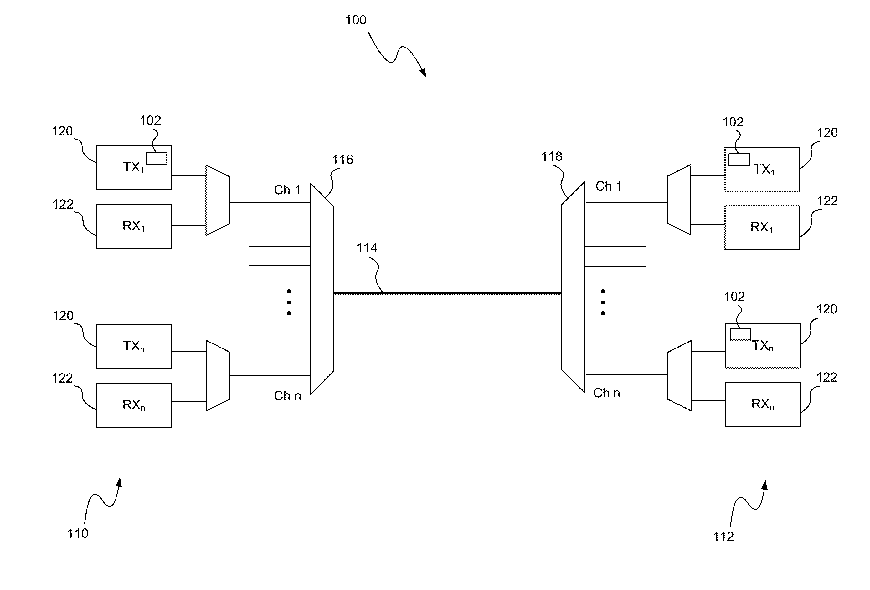
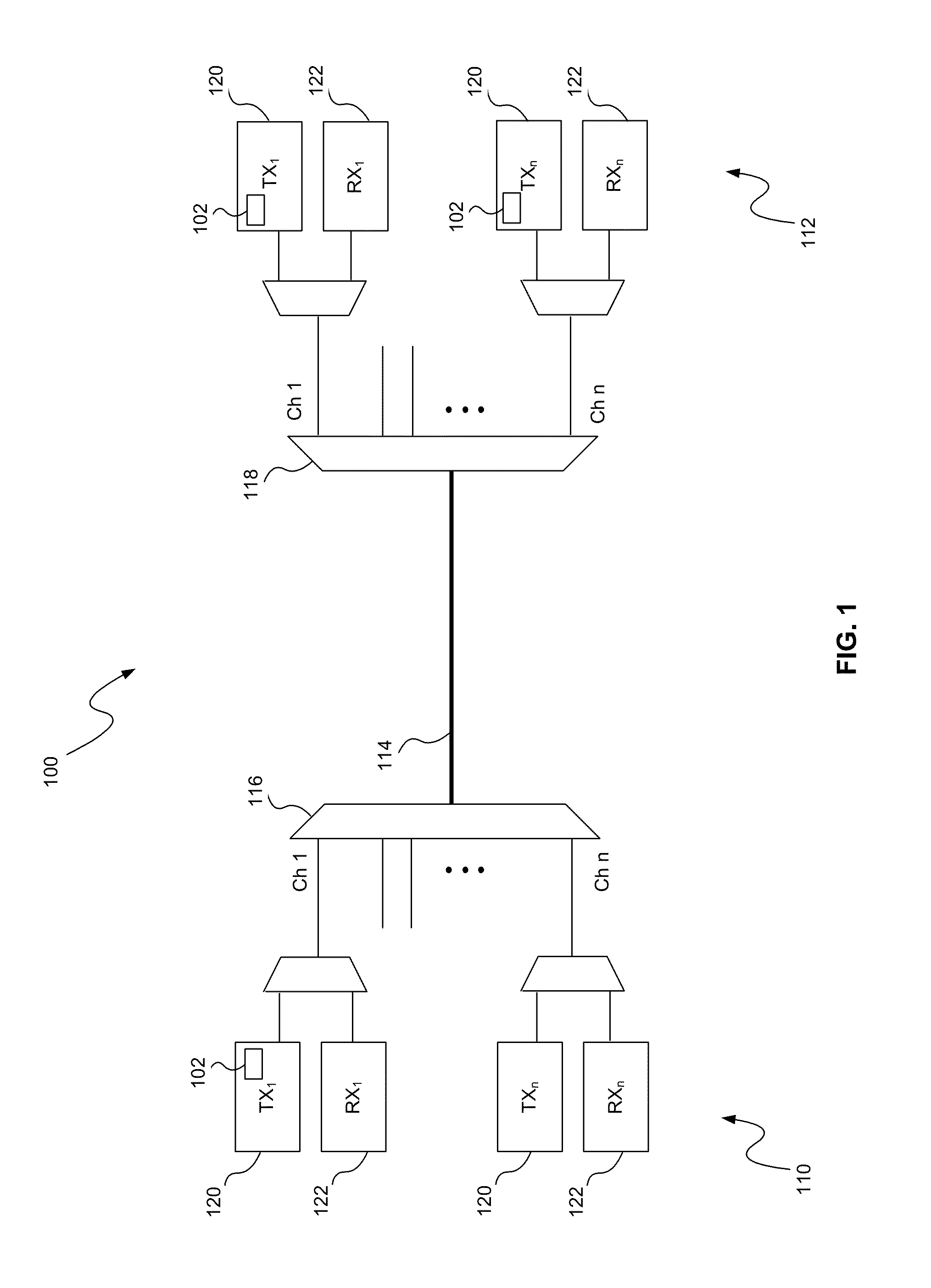
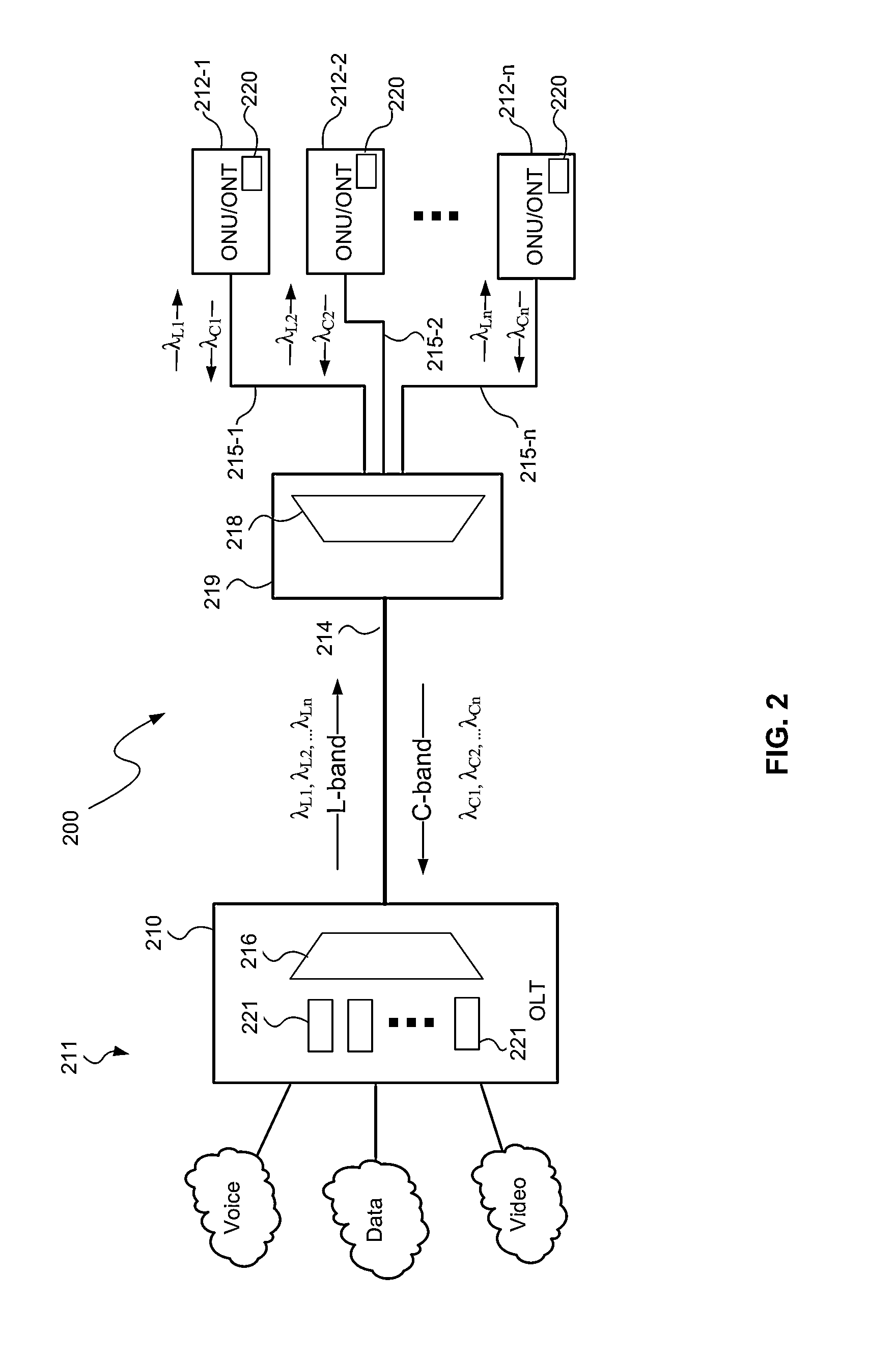
[0019]An external cavity laser array system, consistent with embodiments disclosed herein, may be used in a WDM optical system, such as a WDM-PON, for transmitting optical signals at multiple channel wavelengths. The external cavity laser array system generally includes a plurality of laser emitters (e.g., gain chips) optically coupled to and separated from respective exit reflectors (e.g., narrow-band reflectors), thereby forming an array of external cavity lasers with extended lasing cavities. The extended lasing cavities narrow the mode spacing while maintaining a relatively small gain region in the laser emitter capable of higher speed optical modulation. In one embodiment, the exit reflectors may be distributed Bragg reflectors (DBRs) located in the waveguides in an arrayed waveguide grating (AWG). The laser emitters emit a range of wavelengths including multiple channel wavelengths and the DBRs reflect a subset of channel wavelengths including at least a channel wavelength ass...


PUM


Abstract

An external cavity laser array system may be used in a WDM optical system, such as a WDM-PON, for transmitting optical signals at multiple channel wavelengths. The system generally includes a plurality of laser emitters (e.g., gain chips) optically coupled to and separated from respective exit reflectors (e.g., tunable narrow-band reflectors), thereby forming an array of external cavity lasers with extended lasing cavities. The exit reflectors may be distributed Bragg reflectors (DBRs) located in the waveguides in an arrayed waveguide grating (AWG). The laser emitters emit a range of wavelengths including multiple channel wavelengths and the DBRs reflect a subset of channel wavelengths including at least a channel wavelength associated with the laser emitter such that lasing occurs at the subset of channel wavelengths. The AWG then filters the emitted laser light at the associated channel wavelengths.

Description

CROSS-REFERENCE TO RELATED APPLICATIONS[0001]The present application claims the benefit of U.S. Provisional Patent Application Ser. No. 61 / 527,587 filed on Aug. 25, 2011 (Attorney Docket No. PAT152P) and is a continuation-in-part of U.S. patent application Ser. No. 13 / 543,259 filed on Jul. 6, 2012 (Attorney Docket No. PAT146US), which claims the benefit of U.S. Provisional Patent Application Ser. No. 61 / 508,014 filed on Jul. 14, 2011 (Attorney Docket No. PAT146P), U.S. Provisional Patent Application Ser. No. 61 / 508,008 filed on Jul. 14, 2011 (Attorney Docket No. PAT144P), and U.S. Provisional Patent Application Ser. No. 61 / 508,011 filed on Jul. 14, 2011 (Attorney Docket No. PAT145P), all of which are fully incorporated herein by reference.TECHNICAL FIELD[0002]The present invention relates to wavelength division multiplexed (WDM) optical systems, networks, and methods and more particularly, to an external cavity laser array system for use therein.BACKGROUND INFORMATION[0003]Optical c...

Claims


Application Information

Patent Timeline
Patent Type & Authority Applications(United States)
IPC IPC(8): H04B10/572H01S5/14
CPCH04B10/572H01S5/141H01S5/146H04B10/503H04J14/02H04J14/0246H04J2014/0253H04J14/0282H04B10/506H01S3/1055H01S5/0268H01S5/0612H01S5/4062H04J14/025
Inventor HWANG, WEN-YEN
Owner APPLIED OPTOELECTRONICS
Why Eureka
Try Eureka