Gas cell and coating method of gas cell
- Summary
- Abstract
- Description
- Claims
- Application Information
AI Technical Summary
Benefits of technology
Problems solved by technology
Method used
Image
Examples
modified example 1
3-1. Modified Example 1
[0058]In the above described embodiment, OTS has been used as the first molecules having functional groups to be chemically bonded to the polar groups of the inner walls of the gas cells and non-polar groups, however, the carbon number of its alkyl group is not limited to that. The first molecules may be another silane coupling agent such as dichlorodimethylsilane, dichlorooctadecylsiloxane, or methyltrichlorosilane. Further, the first molecules may be molecules that express the so-called anchor effect, not limited to the silane coupling agent.
[0059]Furthermore, in the above described embodiment, the paraffin has been used as the non-polar second molecule, however, the second molecules are not limited to paraffin. For example, another hydrocarbon may be used. The second molecules may be any non-polar second molecules.
[0060]In addition, in the above described embodiment, the gas cell (gas cell array) formed using the material such as quartz glass or borosilicat...
modified example 2
3-2. Modified Example 2
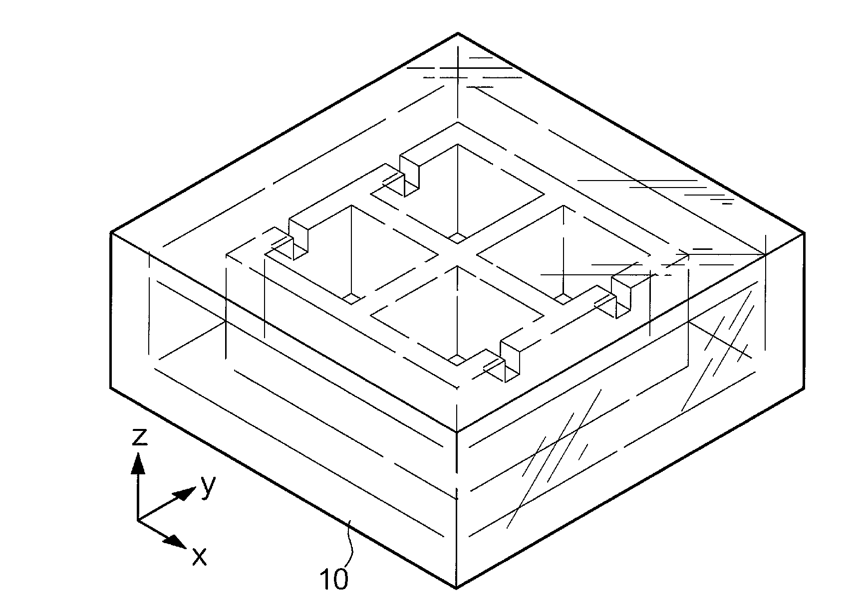
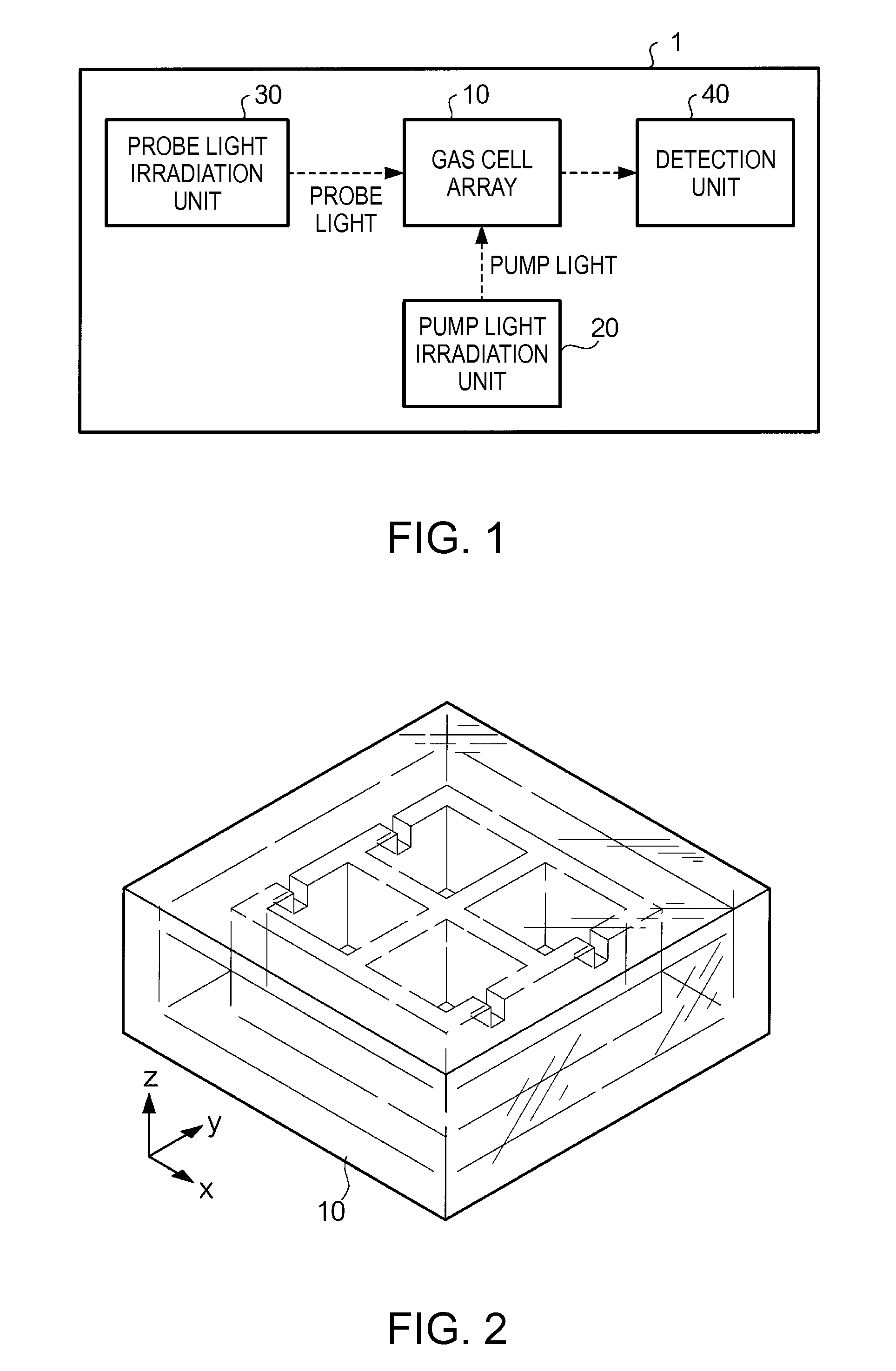
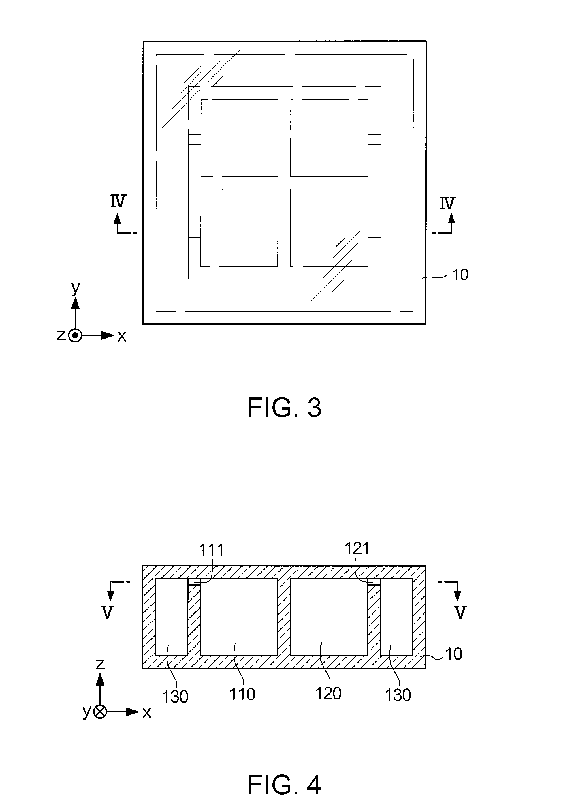
[0061]FIG. 15 is an appearance view of a gas cell array 15 according to modified example 2. FIG. 16 is a sectional view of the gas cell array 15 along XVI-XVI. The shape of the gas cell array is not limited to that explained in the embodiment. The gas cell array 15 has a dummy cell 160 in place of the dummy cell 130. The dummy cell 160 is different from the dummy cell 130 of the gas cell array 10 in a positional relationship with the group of gas cells. Note that the dummy cell refers to a cell that does not contribute to measurement of the magnetic field, but is for holding an ampule. The gas cell array 15 has a gas cell 110, a gas cell 120, a gas cell 140, and a gas cell 150, and the dummy cell 160. The group of cells including the gas cell 110, the gas cell 120, the gas cell 140, and the gas cell 150 are two-dimensionally arranged (arranged in a matrix form) on the xy plane. With respect to the group of cells, the dummy cell 160 is stacked on the group of c...
modified example 3
3-3. Modified Example 3
[0063]The specific details of the ampule breaking step are not limited to those explained in the embodiment. The ampule 200 may have a part in which two materials having different coefficients of thermal expansion are bonded. In this case, at the ampule breaking step, the ampule 200 (the entire gas cell array holding it) is heated in place of laser beam application. At heating, heat to a degree of breaking the ampule 200 due to the difference in coefficient of thermal expansion is applied.
[0064]Further, the breaking of the ampule is not limited to that by the laser beam application. The ampule may be broken by applying dynamic impact or vibration so that the ampule 200 may collide with the inner wall of an ampule container 53. In another example, heat for generating thermal stress may be applied to the ampule 200, and the ampule 200 may be broken by the thermal stress.
PUM
 Abstract
Description
Claims
Application Information
 - R&D
- Intellectual Property
- Life Sciences
- Materials
- Tech Scout
- Unparalleled Data Quality
- Higher Quality Content
- 60% Fewer Hallucinations
Browse by: Latest US Patents, China's latest patents, Technical Efficacy Thesaurus, Application Domain, Technology Topic, Popular Technical Reports.
© 2025 PatSnap. All rights reserved.Legal|Privacy policy|Modern Slavery Act Transparency Statement|Sitemap|About US| Contact US: help@patsnap.com


