Electromagnetic contactor, electromagnetic contactor gas encapsulating method, and electromagnetic contactor manufacturing method

a technology of electromagnetic contactor and gas encapsulation chamber, which is applied in the direction of electromagnetic relay details, air-break switches, relays, etc., can solve the problems of increasing the amount of encapsulated gas consumed, the size of the gas encapsulation chamber b>14/b> is also unavoidably large, and the time for evacuating and charging the gas encapsulation chamber is considerable, so as to reduce the time for encapsulation and reduce equipment cost a gas encapsulation of electromagnetic contactor gas encapsulation of electromagnetic contactor gas encapsulation of electromagnetic contactor gas encapsulation of electromagnetic contactor, electromagnetic contactor, electromagnetic contactor, electromagnetic contactors, electromagnetic contactors, etc., reduce the effect of encapsulation time reduces the effect of encapsulation tim

Inactive Publication Date: 2013-09-12
FUJI ELECTRIC CO LTD +1
View PDF15 Cites 10 Cited by
  • Summary
  • Abstract
  • Description
  • Claims
  • Application Information

AI Technical Summary

Benefits of technology

[0021]According to one aspect of the invention, a device or gas encapsulation chamber for encapsulating and evacuating gas, such as with the gas encapsulating type projection welding method, becomes unnecessary, and it is possible to contribute to a reduction in equipment cost and gas consumption by eliminating accompanying equipment, as well as a reduction in time for encapsulating and evacuating gas, and the like, is possible, meaning that the production rate greatly improves. Also, in the case of gas encapsulating type laser welding, laser welding inside a supply and evacuation chamber becomes unnecessary, and the kind of laser welding in which technological precision is also required, such as the C-shaped supply and evacuation hole, also becomes unnecessary. In other words, it is possible to obtain the same kind of advantage as with the gas encapsulating type projection welding. Furthermore, with regard to spatter, fumes, and the like generated when laser welding, welding is carried out in the air, meaning that a normally used evacuation device is sufficient, and cleaning and maintenance inside the chamber also become unnecessary.
[0022]Also, with regard to the encapsulation of a high pressure gas inside the capsule structure, as with the gas encapsulating types of projection welding method and laser welding method, the gas encapsulation method of the invention has no problem of a reduction in mass productivity and as far as maintaining gas pressure is concerned, pressure can be set and regulated as desired, meaning that a considerable improvement in productivity is possible.
[0023]Meanwhile, with regard to the heretofore known method of installing the pipe in the base plate described in the background art, two brazing steps are necessary—brazing the ceramic arc extinguishing chamber and the base plate having a protruding portion, and brazing (or soldering) the base plate and the pipe. With the manufacturing method of the invention, however, it is possible for all brazing steps to be carried out only on the arc extinguishing chamber side, and thus possible to reduce the assembling steps for the manufacturing process. That is, as the pipe brazing step can be carried out in a furnace together with the brazing of the fixed terminal and connection member, it is possible to simplify the work.

Problems solved by technology

Because of this, there is a problem in that the gas encapsulation chamber 14 is also unavoidably of a large size.
Because of this, there is a problem in that a considerable time is needed for the evacuating and charging of the gas encapsulation chamber.
With this kind of step, there is a problem in that the amount of encapsulated gas consumed also increases.
Because of this, it cannot be said that the gas encapsulating type of laser welding is a technologically easy manufacturing method.
Also, as laser welding is carried out through the transparent glass window 22 of the chamber 21, a large amount of spatter, fumes, and the like, are generated when welding, meaning that there is a problem in that the transparent glass window 22 becomes dirty, and the inside of the chamber 21 becomes dirty easily.
With this method, however, there is also a problem in that the size of the chamber increases.
However, when the gas encapsulation pressure becomes a gas pressure of a few atmospheres or more higher again, it becomes difficult to carry out seal welding with good mass productivity, while maintaining the gas encapsulation pressure, in the gas encapsulation chamber of the heretofore described kind of gas encapsulating type projection welding method and the chamber of the laser welding method.
In particular, as brazing or soldering is a separate step requiring air tightness, unnecessary time is taken.

Method used


Image

  • Electromagnetic contactor, electromagnetic contactor gas encapsulating method, and electromagnetic contactor manufacturing method
  • Electromagnetic contactor, electromagnetic contactor gas encapsulating method, and electromagnetic contactor manufacturing method
  • Electromagnetic contactor, electromagnetic contactor gas encapsulating method, and electromagnetic contactor manufacturing method

Examples


first embodiment

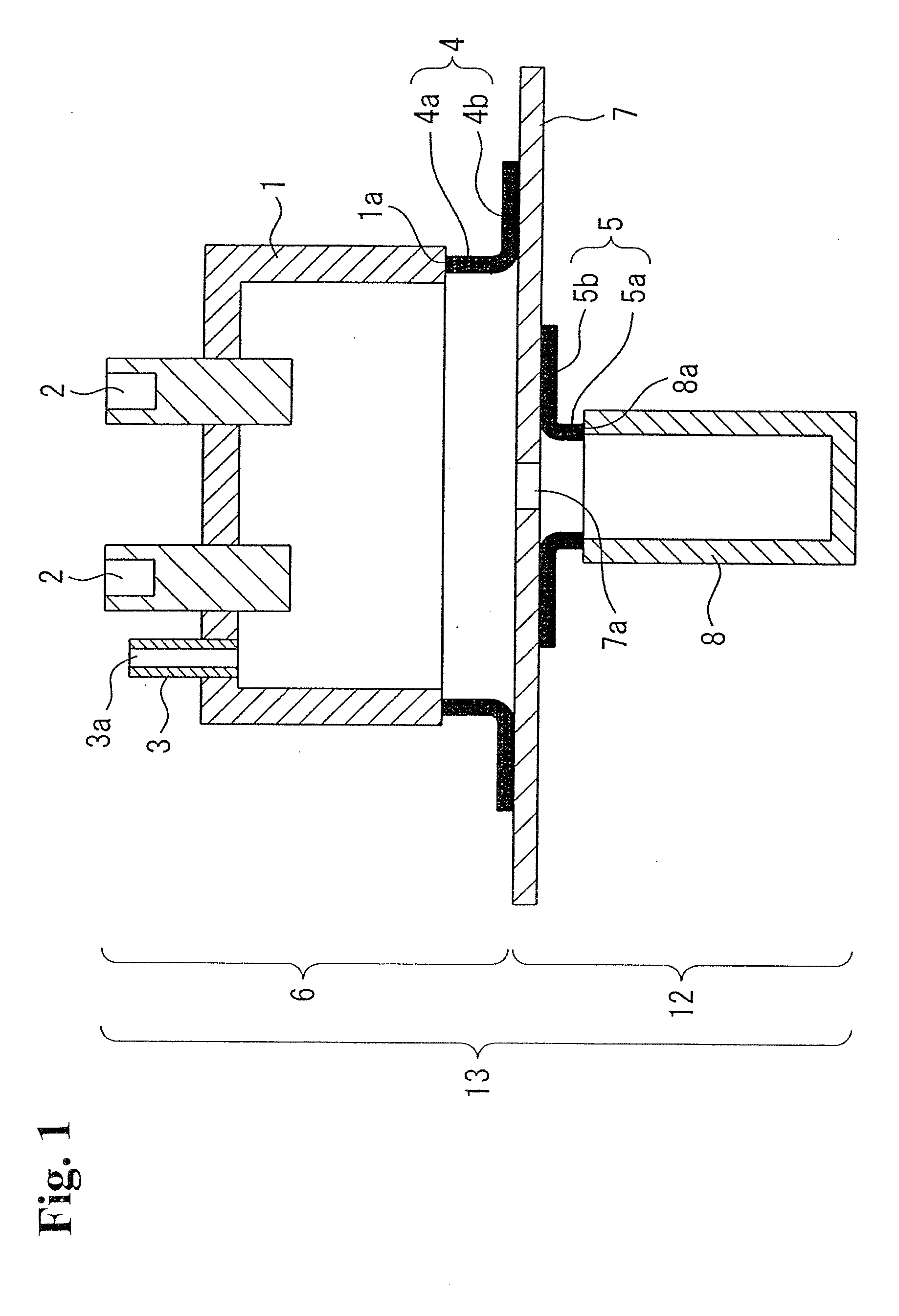
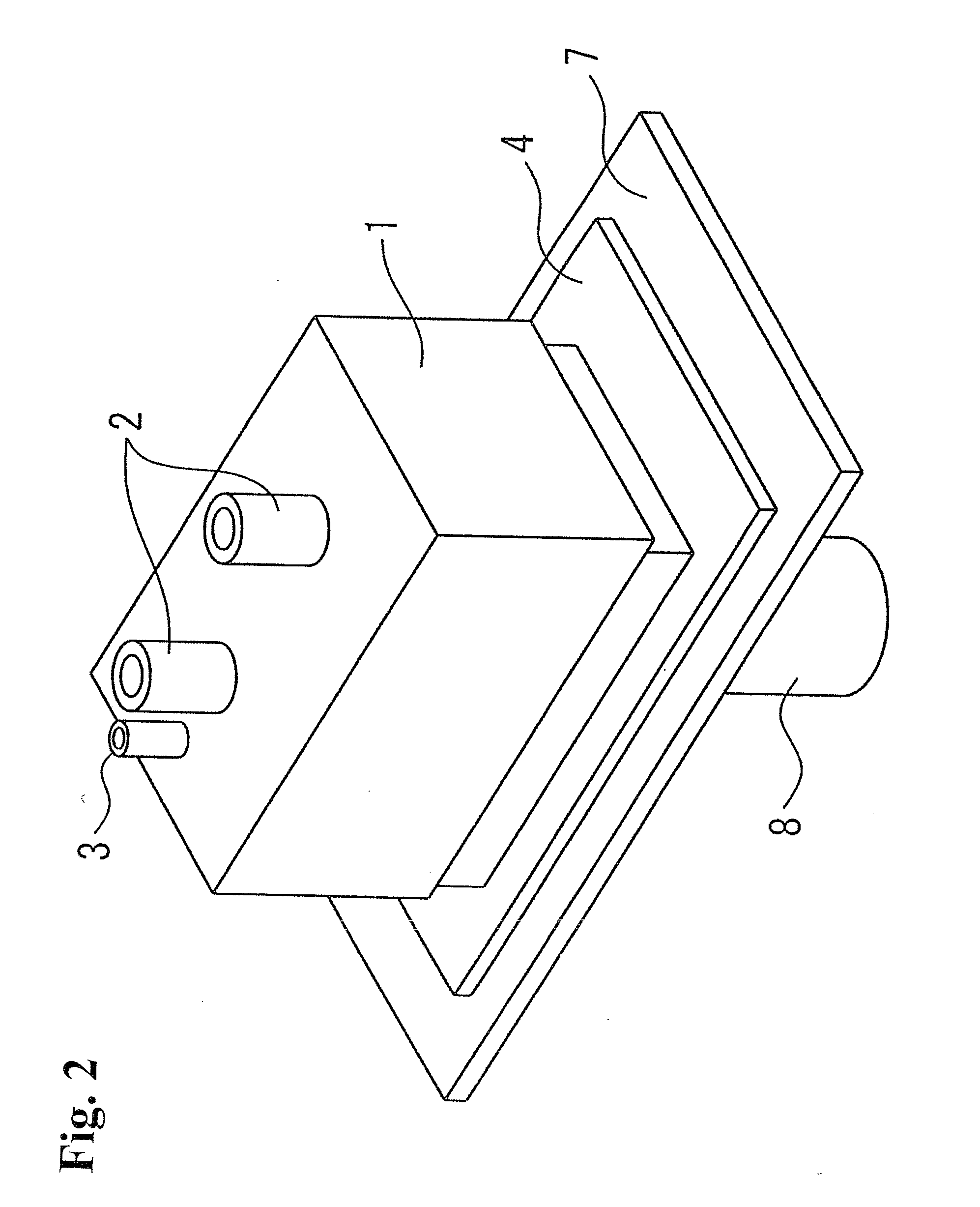
[0048]In this way, it is possible to simultaneously braze the fixed terminals 2, pipe 3, and first connection member 4 to the arc extinguishing chamber 1. Because of this, it is possible for the connection of the fixed terminals 2 and pipe to the arc extinguishing chamber 1 and the formation of the arc extinguishing chamber connection portion 6 to be carried out simultaneously, and thus possible to simplify the step of forming the arc extinguishing chamber 1 and arc extinguishing chamber connection portion 6. Also, the encapsulating of gas in the arc extinguishing chamber 1 and cap 8 can also be carried out easily.

[0049]In the first embodiment, a description has been given of a case wherein the pipe 3 is fixed penetrating the upper side wall of the arc extinguishing chamber 1 but, not being limited to this, the pipe 3 may be joined penetrating a wall surface in a direction perpendicular to the fixed terminals 2 fixed to the arc extinguishing chamber 1, as shown in FIG. 3(a). When j...

second embodiment

[0053]Next, a description will be given of the invention, based on FIG. 4.

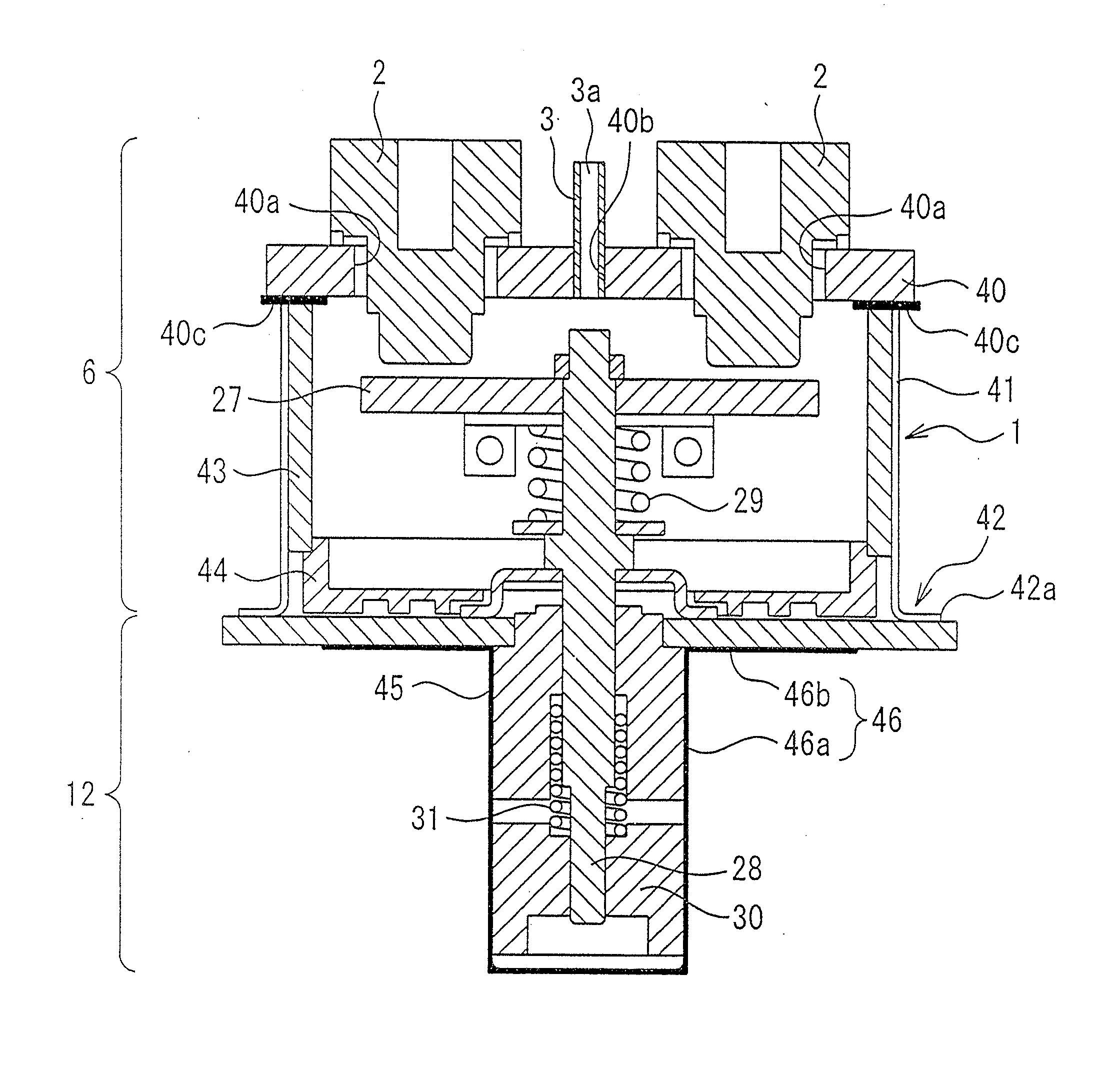
[0054]The second embodiment is such that, instead of the case wherein the tub-like arc extinguishing chamber is formed integrally, the arc extinguishing chamber is formed of a terminal support insulating substrate and a third connection member.

[0055]That is, in the second embodiment, a fixed terminal support insulating substrate 40 is included. Through holes 40a that fix the pair of fixed terminals 2 and a through hole 40b that fixes the pipe 3 are formed in the fixed terminal support insulating substrate 40. Also, the fixed terminal support insulating substrate 40 is configured as a ceramic insulating substrate by a metalizing process being carried out with a metal such as copper foil on a plate-like ceramic base in which the through holes 40a and 40b are formed, around the through holes 40a and 40b and on an outer peripheral edge portion 40c of one surface.

[0056]Further, the fixed terminals 2 are inserted in...


PUM

PropertyMeasurementUnit
pressureaaaaaaaaaa
sizeaaaaaaaaaa
timeaaaaaaaaaa

Abstract

An electromagnetic contactor has a base plate having an aperture hole; an arc extinguishing chamber having a fixed terminal and a pipe; and a bottomed tubular cap in which one end thereof is open. An arc extinguishing chamber connection portion is formed by the arc extinguishing chamber and a first connection member having a tube portion connected to the arc extinguishing chamber and a flange portion contacting with the base plate. A cap connection portion is formed by the cap and a second connection member having a tube portion connected to the cap and a flange portion connected to the base plate. The flange portions of the first and second connection members are attached to one surface and the other surface of the base plate accordingly. The arc extinguishing chamber connection portion and the cap connection portion are in communication through the aperture hole of the base plate.

Description

TECHNICAL FIELD[0001]The present invention relates to an electromagnetic contactor including a contact device that includes a fixed contact and movable contact interposed in a current path, and in particular, relates to the electromagnetic contactor, a gas encapsulating method whereby gas is encapsulated inside the electromagnetic contactor, and an electromagnetic contactor manufacturing method.BACKGROUND ART[0002]A heretofore known gas encapsulating structure (hereafter called a capsule structure) of an electromagnetic contactor is the kind of structure shown in FIG. 5 wherein, specifically, a fixed contact 26, a movable terminal 27 having a movable contact 27a, a movable shaft 28, a contact spring 29, and the like, are incorporated inside an arc extinguishing chamber 1. Also, a movable iron core 30 and return spring 31 to which the movable shaft 28 is linked are incorporated inside a cap 8. No description will be given of details at this point.[0003]Firstly, the arc extinguishing ...

Claims


Application Information

Patent Timeline
Patent Type & Authority Applications(United States)
IPC IPC(8): H01H33/60
CPCH01H1/66H01H9/346H01H49/00H01H50/02H01H50/54Y10T29/49213H01H33/60H01H11/04H01H69/00H01H33/04H01H2050/025H01H50/60H01H11/00
Inventor IMAMURA, SEIJIOKAMOTO, KOUICHIOGAWA, TAKUYAMAMOTO, YUICHITAKAYA, KOUETSU
Owner FUJI ELECTRIC CO LTD
Why Eureka
Try Eureka