Device for disinfecting gases and/or liquids

a technology for disinfecting devices and liquids, applied in the direction of specific water treatment objectives, filter regeneration, water/sludge/sewage treatment, etc., can solve the problems of limiting the life of the device, reducing the efficiency of the method, and unable to replace the uv light source in time, so as to achieve the effect of small highly compact systems and increased efficiency

Active Publication Date: 2013-09-12
SCHOTT AG
View PDF4 Cites 45 Cited by
  • Summary
  • Abstract
  • Description
  • Claims
  • Application Information

AI Technical Summary

Benefits of technology

[0099]The device shows its advantages in particular in smaller highly compact systems, for example with pressures in the domestic field. The device according to the present invention clearly increases the degree of efficiency compared to known applications.

Problems solved by technology

A problem in the direct contact of UV-light source and medium to be treated is in that the surface of the UV-light source must be resistant against the medium and must be sealed against same.
In such a case the hot liquid causes even additional heating of the UV-LEDs and can thereby clearly limit their life span.
The described treatment systems also have the disadvantage here that no simple replacement of the UV-light source can occur, since this is in direct contact with the medium to be treated.
Shutting down the entire system is therefore required, thereby reducing the efficiency of the method.
The UV-light sources are hereby again in direct contact with the fluid to be treated, resulting in the already described disadvantages.
Disadvantages of known systems of type (b) are low efficiency and large space requirement.
Systems known from the current state of the art however, typically have the problem of poor utilization of UV light, caused by shading, multiple reflections and loss mechanisms, in particular on the reflective surfaces of the reflector system.
This portion of UV-radiation is lost and is no longer available to disinfect.
Moreover, the known arrangements of UV-light sources and reflectors require a lot of space and are therefore suitable only to a limited extent for applications requiring a small space.

Method used


Image

  • Device for disinfecting gases and/or liquids
  • Device for disinfecting gases and/or liquids
  • Device for disinfecting gases and/or liquids

Examples


Embodiment Construction

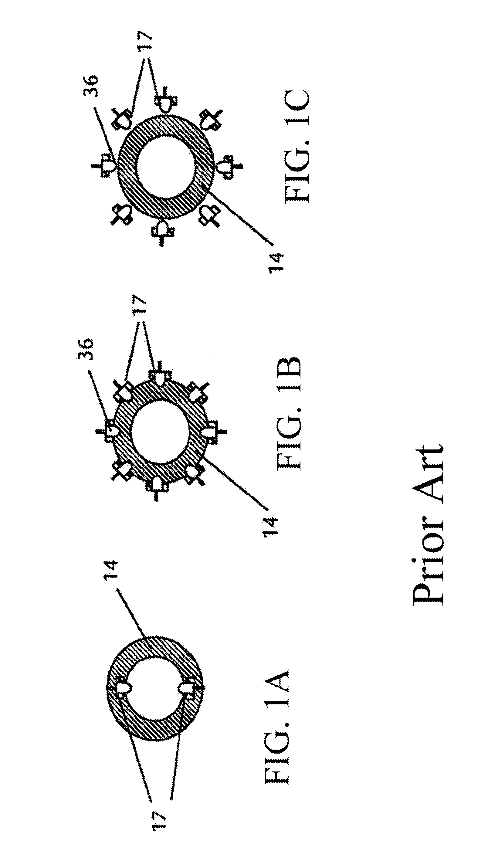
[0110]Referring now to the drawings, and more particularly to FIGS. 1a, 1b and 1c, there is shown in each a schematic cross sectional view of exemplary embodiments from the current state of the art according to DE 10 2010 005 893 A1 (FIGS. 6b, 6c and 6d of said documentation). FIG. 1a depicts a UV-radiation unit which shows UV-radiation unit 17 integrated into the wall of conduit system 14. UV-radiation devices 17 respectively protrude with their tip area into the tube interior. The light sources are therefore in direct contact with the medium flowing in the interior space and must be permanently sealed against same. A simple replacement is no longer easily possible. The system must be shut down for this purpose.

[0111]FIG. 1b illustrates a multitude of UV-radiation devices 17 in the embodiment of UV-LEDs 36 which are integrated into the wall of conduit system 14. UV-LEDs 36 are therefore located in recesses of the tube wall. The illustrated recesses from the current state of the art...


PUM

PropertyMeasurementUnit
wavelengthaaaaaaaaaa
wavelengthsaaaaaaaaaa
thicknessaaaaaaaaaa

Abstract

A device for disinfecting of gases and/or liquids, includes a tube of UV-transparent glass having a hollow interior space and a tube wall with a tube inside wall and a tube outside wall, as well as at least one UV-light source. The UV-transparent glass tube has an indentation extending into the interior space on at least one location and in the at least one indentation at least one UV-light source is arranged. The geometry causes the UV-light sources to be closer to the medium to be disinfected, so that a large portion of the UV-light reaches the interior space on a direct path through the glass, thus allowing for a low-loss transfer of the UV-light.

Description

BACKGROUND OF THE INVENTION[0001]1. Field of the Invention[0002]The present invention relates to a device for disinfecting of gases and / or liquids.[0003]2. Description of the Related Art[0004]An already known method is to utilize ultraviolet (UV) radiation for treatment, in particular disinfecting or respectively sterilizing water, air or surfaces. Drinking water treatment by means of UV-radiation has hitherto been relatively common, whereby the germination index in the water can be greatly reduced reliably and dependent upon the dose. UV-radiation inactivates micro-organisms such as pathogens, in particular bacteria or viruses.[0005]UV-disinfection offers a series of advantages compared to conventional disinfection, based on chemical processes. UV-disinfection is a simple and rapidly effective process whereby disinfection occurs immediately during the exposure of the medium. Another great advantage of UV-disinfection is that neither taste, odor, nor pH-value of the disinfected medi...

Claims


Application Information

Patent Timeline
Patent Type & Authority Applications(United States)
IPC IPC(8): B01D53/00A61L2/10C02F1/32
CPCC02F1/32C02F1/325C02F2303/04C02F2201/3222C02F2201/3227C02F2201/3228A61L9/20B01D53/007A61L2/10A61L2/08A61L2/26
Inventor BLECHSCHMIDT, JORGBARTSCH, REINER
Owner SCHOTT AG
Why Eureka
Try Eureka