Flow regulation vent

a vent and flow regulation technology, applied in the field of vent valve apparatus, can solve the problems of excessive noise, more gas passing, and existing prior art vents, and achieve the effects of increasing mask pressure, natural rigidity, and spring resistance against bending of the flap

Inactive Publication Date: 2013-09-19
RESMED LTD
View PDF9 Cites 6 Cited by
  • Summary
  • Abstract
  • Description
  • Claims
  • Application Information

AI Technical Summary

Benefits of technology

[0025]The housing includes a vent orifice positioned beneath the free portion of the flap with a portion of the housing surrounding the vent orifice being curved. While flexible, the flap has a level of natural rigidity that will provide a spring resistance against bending of the flap. In a relaxed state, the free portion of the flap will leave the vent orifice uncovered and a gas flow area between the vent orifice and the flap will be at a maximum. When the CPAP system is in use a force will act against the spring resistance of the flap and the free portion of the flap will tend to move toward the vent orifice. As the free portion of the flap moves closer to the vent orifice with increasing mask pressure, it follows the curved surface of the housing, progressively closing the vent orifice and reducing the gas flow area between the vent orifice and the flap. The interaction between the increasing mask pressure and decreasing gas flow area acts to reduce the gas flow rate through the vent as compared to the flow that would be achieved with a vent of constant gas flow area.
[0026]An alternative embodiment of the flow regulation vent of the present invention opens an auxiliary exhalation vent orifice during exhalation to allow higher exhalation gas flow to atmosphere. An embodiment may also include a non-rebreath valve or anti-asphyxias valve function that reduces or eliminates exhaled gas being retained in the gas circuit after the end of exhalation. These embodiments serve the desired aim of eliminating or at least reducing the occurrence of a user rebreathing exhaled gas.
[0028]The flow regulation vent of the present invention is simple and inexpensive to manufacture but provides effective, easily tailored flow regulation. The flow regulation vent reduces operating noise of the CPAP system by reducing the volume of gas flow required from the flow generator at high pressures, as well as thus reducing the work output of the flow generator. The vent also reduces rebreathing of CO2 and other exhaled gas and provides for faster air pressure rise time, increasing the effectiveness of the CPAP system and patient compliance with CPAP treatment.

Problems solved by technology

Increasing CPAP pressure results in more gas passing through the vent which in turn creates more noise.
Existing prior art vents can produce excessive noise when CPAP pressures are raised above about 4 cm H2O.
This noise can adversely affect patient and bed-partner comfort.
At higher pressures, existing vents are also inefficient as they allow more gas through the vent than is required for adequate exhaust gas washout and thereby require the flow generator to provide more flow than is necessary in order to maintain the required treatment pressure.
Further, where treatment gas is being supplied, such as oxygen, surplus treatment gas is vented and thereby wasted unnecessarily.
The flow of gas from the gas delivery system through the vent to atmosphere creates noise as the delivered gas, and upon expiration the patient expired gas including CO2, passes through the vent to atmosphere.
Typically this selection involves a compromise being struck between the choice of a vent size that is sufficiently large to achieve an adequate flow rate at the low end of the pressure range and yet cause no greater than an acceptable noise level as the pressure increases through the pressure range.
In short, where the vent size is chosen to deliver a quiet gas wash out flow rate at the higher pressure levels of the pressure range it may be inadequate to allow acceptable wash out flow at the desired lowest end of the pressure range.
Also a vent with sufficient size to achieve an adequate wash out flow rate at pressures low in the pressure range tend to generate unacceptable noise at the desired higher end of the pressure range.
In addition the choice of a larger vent dictates that the source of gas have capacity to deliver the requisite flow rates for the higher pressure levels and as such the gas source will tend to consume more power and generate louder noise and require additional noise attenuating features so as to keep the total noise within acceptable limits.
Because of this it can be undesirable to change from a mask specified for the control algorithm for concern that the new mask should introduce a vent characteristic which is not within the operating parameters of the control algorithm.
This inability to change masks because of the accompanying introduction of unknown or incompatible vent characteristics can be adverse to patient compliance with CPAP treatment.
This is because a patient may only tolerate CPAP treatment where it is delivered through a particular mask and that mask is incompatible with the prescribed CPAP system control algorithm.

Method used


Image

  • Flow regulation vent
  • Flow regulation vent
  • Flow regulation vent

Examples


Embodiment Construction

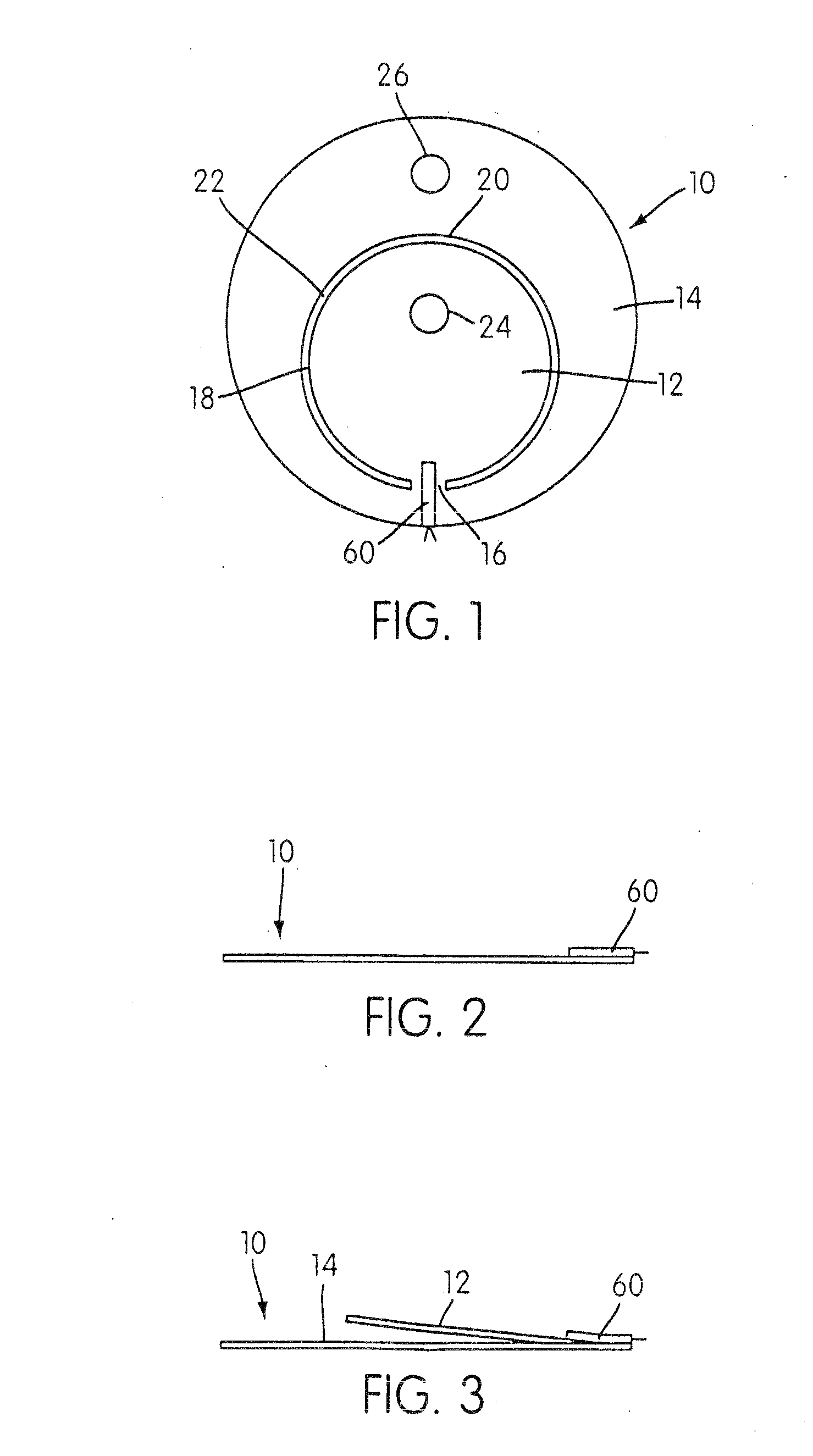
[0072]A flow regulation vent 10 is shown in FIGS. 1-3, and, in this embodiment, is circular. The flow regulation vent 10 is constructed from a unitary sheet of material and includes a movable portion 12 pivotally attached at one end to a fixed portion 14 by unitary hinge 16. Movable portion 12 has an outer perimeter 18, which, in the embodiment shown, is substantially circular. Fixed portion 14 includes an orifice 20, which, in the embodiment shown, is also substantially circular and which is slightly larger in diameter than the diameter of the outer perimeter 18 to provide a gap 22 therebetween when the movable portion is in a fully pressurized position. See FIG. 2, which shows a side view of the vent 10 when in the fully pressurized position. Movable portion 12 can optionally include one or more bleed orifices 24 and fixed portion 14 can optionally include one or more bleed orifices 26.

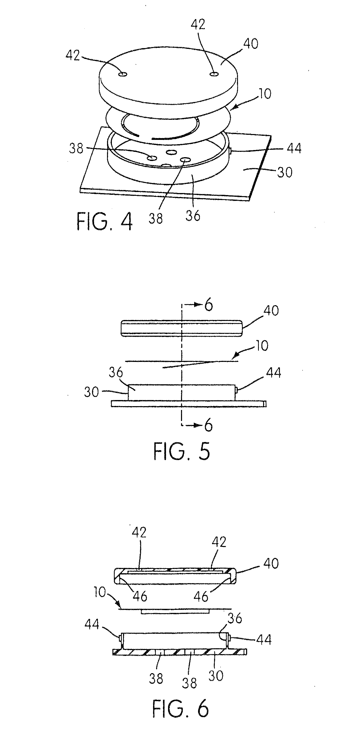
[0073]FIG. 4 shows the flow regulation vent 10 in an exploded perspective view in combination wi...


PUM


Abstract

A flow regulation vent includes a fixed portion adapted to engage a gas supply conduit and a spring force biased movable portion connected by a hinge to the fixed portion and flowingly connected to the pressurized gas supply. The fixed portion includes a gas flow orifice. The movable portion is pivotably movable between 1) a relaxed position, wherein at a specified minimum operating pressure, the movable portion is pivoted by the spring force away from the fixed portion to a position to establish a first gas washout flow area between the movable portion and the gas flow orifice; and 2) a fully pressurized position, wherein at a specified maximum operating pressure, the pressurized gas offsets the spring force to pivot the movable portion to a position adjacent the fixed portion to establish a minimum gas washout flow area between the movable portion and the gas flow orifice.

Description

[0001]This application is a continuation of U.S. Ser. No. 10 / 433,980, filed Jun. 10, 2003, now allowed, which is the U.S. national phase of International Application No. PCT / AU01 / 01658 filed Dec. 21, 2001, and claims priority to U.S. Provisional Application No. 60 / 257,171, filed Dec. 22, 2000, the entire contents of each of which are hereby incorporated by reference.FIELD OF THE INVENTION[0002]The present invention relates to a vent valve apparatus for use with a system for supplying breathable gas pressurized above atmospheric pressure to a human.[0003]The invention has been developed primarily for use in controlling the venting of washout gas in a continuous positive airway pressure (CPAP) gas delivery systems used, for example, in the treatment of obstructive sleep apnea (OSA) and similar sleep disordered breathing conditions.[0004]The invention may also be used in conjunction with suitable mask and gas delivery systems for the application of assisted ventilation treatment.[0005]...

Claims


Application Information

Patent Timeline
Patent Type & Authority Applications(United States)
IPC IPC(8): A61M16/20A61M16/06A61M16/00
CPCA61B5/0876A61M16/06A61M16/208A61M2016/0042A61M16/0633A61M2205/42A61M2210/0618G01F1/28A61M16/0057A61M2205/332A61M16/0825A61M16/0616A61M16/0622A61M16/0816A61M16/0875
Inventor DANTANARAYANA, MUDITHA PRADEEPNASR, SAAD
Owner RESMED LTD
Why Eureka
Try Eureka