Electrospinning Process for Manufacture of Multi-Layered Structures

a multi-layered structure and electrospinning technology, applied in the field of fiber structures, can solve the problems of limited throughput and inability to achieve drug-loaded core-sheath fibers. , to achieve the effect of improving the efficiency of emulsion-based electrospinning methods, the throughput of both emulsion-based electrospinning

Active Publication Date: 2013-09-19
ARSENAL MEDICAL
View PDF0 Cites 30 Cited by
  • Summary
  • Abstract
  • Description
  • Claims
  • Application Information

AI Technical Summary

Benefits of technology

[0006]The present invention addresses the need described above by providing systems and methods for high-throughput production of core-sheath fibers.

Problems solved by technology

None of these methods, however, are ideally suited to producing drug-loaded core-sheath fibers, as they all utilize high temperatures which may be incompatible with thermally labile materials such as drugs or polypeptides.
Core-sheath fibers have been produced using emulsion-based electrospinning methods, which exploit surface energy to produce core-sheath fibers, but which are limited by the relatively small number of polymer mixtures that will emulsify, stratify, and electrospin.
However, both emulsion and coaxial electrospinning methods can have relatively low throughput, and are not ideally suited to large-scale production of core-sheath fibers.
To increase throughput, coaxial nozzle arrays have been utilized, but such arrays pose their own challenges, as separate nozzles may require separate pumps, the multiple nozzles may clog, and interactions between nozzles may lead to heterogeneity among the fibers collected.
The Nanospider® improves throughput relative to other electrospinning methods, but it is not currently possible to manufacture core-sheath fibers using the Nanospider®.

Method used


Image

  • Electrospinning Process for Manufacture of Multi-Layered Structures
  • Electrospinning Process for Manufacture of Multi-Layered Structures
  • Electrospinning Process for Manufacture of Multi-Layered Structures

Examples


example 1

Electrospinning Conditions for Various Slit / Hole Geometries

[0057]Slit-surfaces of various geometries were fabricated and the formation of electrospinning jets from these surfaces was demonstrated. FIG. 10 shows slit-surfaces that are (A) continuously linear, (B) continuously circular, (C) continuously linear with holes, and (D) non-continuous holes. The respective dimensions of slits or holes and the electrospinning conditions used therefore are presented in Table 1, below:

TABLE 1GEOMETRIES AND ELECTROSPINNING CONDITIONSFOR APPARATUSES SHOWN IN FIG. 10:SlitApparatusPolymerSlitElectricGeometryGeometrysolutiondimensionsFlow rateFlow SourcefieldContinuouslyWedge6 wt % PLGA0.5 mm ×60 ml / hrUnderneath40 kVlinear75 / 25 in TFE35 mmContinuouslyAnnular or2 wt % PLGA1 mm ×120 ml / hr Underneath40 kVcircularShowerhead85 / 15 in80 mmChloroform / Methanol(6:1)ContinuouslyTube2.5 wt % PLGA8 cm long30 ml / hrEnds40 kVlinear with85 / 15 inholesChloroform / Methanol(6:1)Non-Tube2.5 wt % PLGA5 cm long20 ml / hrEnds4...

example 2

Achieving Even Flow of Polymer Solutions Using Mechanical Piston

[0058]Even flow of polymer solution to a slit was achieved by the use of a mechanical piston. FIG. 17A-B depicts the apparatus used. The wedge-shaped slit fixture is attached to a chamber connected to a piston that is mechanically driven using a syringe pump. As the piston moves forward, it pushes solution uniformly towards the slit. Using a flow rate of 50 ml / h and a voltage of 50 kV, multiple electrospinning jets emerged along the entire length of the slit as shown in 25C.

example 3

Achieving Even Flow of Polymer Solutions Using Pressure Diffusers

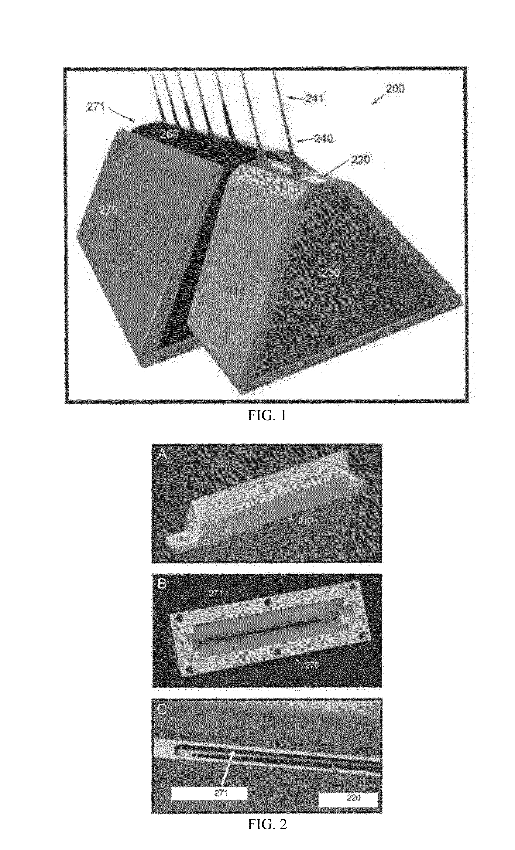
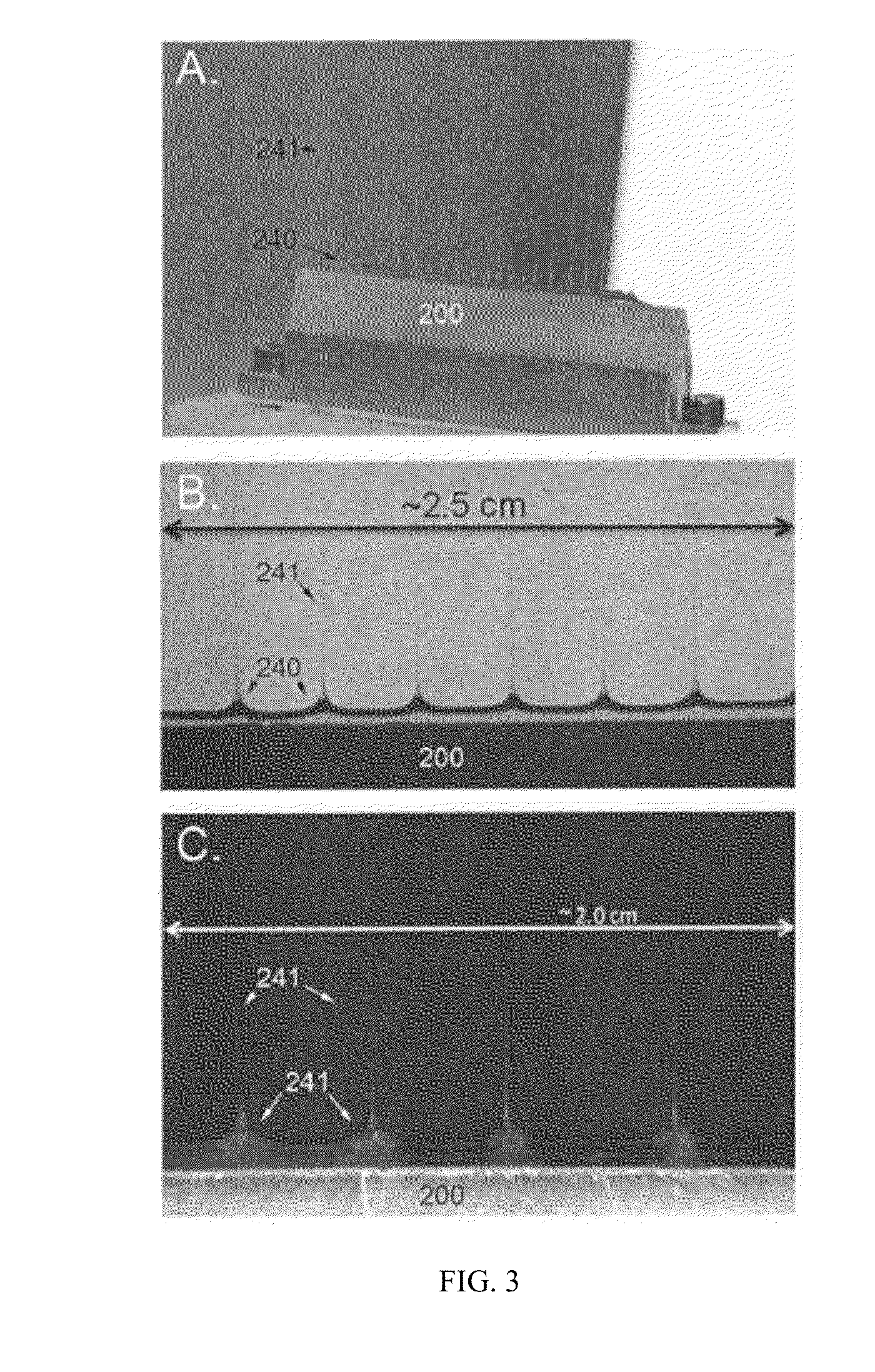
[0059]Even flow of polymer solution to the slit was achieved by incorporating pressure diffusers to divert momentum of fluid flow across the slit. Shown in FIG. 11 are examples of such diffusers. In FIG. 11A, the diffuser is a triangular fixture that contains holes across its length to allow polymer solution to flow through. To demonstrate its ability to divert fluid flow, the diffuser was press-fit inside a container such that flow of solution is forced through its holes rather than around. As shown in FIG. 11B, a dyed solution of PLGA in chloroform:methanol that was pumped into the container from one inlet source encounters the diffuser, spreads across the length of the chamber, and then flows through the holes of the diffuser. The result is a more even distribution of fluid flow across the length of the chamber. Similarly, FIG. 11C shows a circular shaped pressure diffuser that contains holes across its surface. As ...


PUM

PropertyMeasurementUnit
voltageaaaaaaaaaa
voltageaaaaaaaaaa
voltageaaaaaaaaaa

Abstract

Devices and methods for high-throughput manufacture of concentrically layered nanoscale and microscale fibers by electrospinning are disclosed. The devices include a hollow tube having a lengthwise slit through which a core material can flow, and can be configured to permit introduction of sheath material at multiple sites of Taylor cone formation formation.

Description

CROSS REFERENCE TO RELATED APPLICATIONS[0001]The present invention claims priority to U.S. application Ser. No. 13 / 362,467 entitled “Electrospinning Process for Manufacture of Multi-Layered Structures,” filed Jan. 31, 2012.[0002]This invention was made with Government support under 70NANB11H004 awarded by the National Institute of Standards and Technology (NIST). The Government has certain rights in the invention.FIELD OF THE INVENTION[0003]The present invention generally relates to fiber structures and methods of forming fiber structures using wedge-shaped vessels.BACKGROUND[0004]Macro-scale structures formed from concentrically-layered nanoscale or microscale fibers (“core-sheath fibers”) are useful in a wide range of applications including drug delivery, tissue engineering, nanoscale sensors, self-healing coatings, and filters. On a commercial scale, the most commonly used techniques for manufacturing core-sheath fibers are extrusion, fiber spinning, melt blowing, and thermal dra...

Claims


Application Information

Patent Timeline
Patent Type & Authority Applications(United States)
IPC IPC(8): D01D5/00
CPCD01D5/0069D01D5/0061D01D5/34D01D5/0038
Inventor SHARMA, UPMAPHAM, QUYNHMARINI, JOHNYAN, XURICORE, LEE
Owner ARSENAL MEDICAL
Why Eureka
Try Eureka