
Method and system for treating valve stenosis

a valve stenosis and valve leaflet technology, applied in the field of medical devices and methods, can solve the problems of deteriorating valve leaflet function, and achieve the effects of reducing the opening of leaflets available, increasing the area available for blood flow, and reducing the opening of leaflets

Active Publication Date: 2013-09-26
SPECTRANETICS
View PDF4 Cites 11 Cited by
  • Summary
  • Abstract
  • Description
  • Claims
  • Application Information

AI Technical Summary

Benefits of technology

[0009]The present invention provides improved apparatus and methods for performing valvuloplasty of the aortic and other cardiac valves, such as the pulmonary valve and the mitral valve. Valvuloplasty is the treatment of stenotic cardiac valves by balloon expansion within the valve annulus. Such balloon expansion can open the valve and increase the area available for blood flow by fracturing and displacing stenotic material, such as calcified plaque, which covers the valve leaflets and / or the valve annulus. Such stenotic valves become stiff such that functioning of the valve leaflets deteriorates, including a reduced opening of the leaflets available to allow blood flow during ventricular systole.
[0010]The present invention provides for placement of scoring elements over the exterior surface of a balloon or other expansible shell. The scoring elements, which typically number from six to twenty, are preferably uniformly distributed over the outer surface of the balloon so that they concentrate forces uniformly over the circumference of the valve annulus when the balloon is inflated. Such uniformly concentrated forces are able to effectively fracture and displace the stenotic material to increase the area of the annulus available for blood flow and often to improve the ability of the valve leaflets to function. Additionally, when the scoring elements are incorporated in a self-closing elastic cage which is placed over the balloon, the cage is able to improve balloon deflation characteristics so that the balloon deflates both more rapidly and more uniformly so that balloon flaps and other elements are not exposed during withdrawal of the balloon from the valve annulus and vasculature. The scoring elements also help to stabilize the balloon within the valve annulus during balloon inflation to inhibit slippage which can both reduce the effectiveness of the treatment and expose the valve annulus and surrounding tissue to damage.
[0012]Positioning the expansible shell typically comprises advancing a catheter which carries the expansible shell and scoring elements over the aortic arch and into the aortic valve annulus. The shell expansion will typically be maintained in a period of time from 1 second to 10 seconds, usually from 1 second to 4 seconds, typically for about 2 seconds. When using an inflatable balloon, expanding the shell comprising expanding the balloon, and the scoring elements are typically provided as axial struts in an elastic metal cage surrounding but unattached to the inflatable balloon. The cage is elastically biased to close over the balloon as the balloon is inflated, thus both decreasing the deflation time and improving the rewrap characteristics of the balloon over the placement catheter. In the exemplary embodiments, the balloon is non-distensible and inflated to a pressure in the range from 1 atmosphere to 12 atmospheres, preferably from 4 atmospheres to 12 atmospheres, typically about 8 atmospheres. The balloon will usually carry from six to twenty scoring elements and will be inflated to a diameter in the range from twenty millimeters to thirty millimeters, depending on the size of the valve annulus being treated.
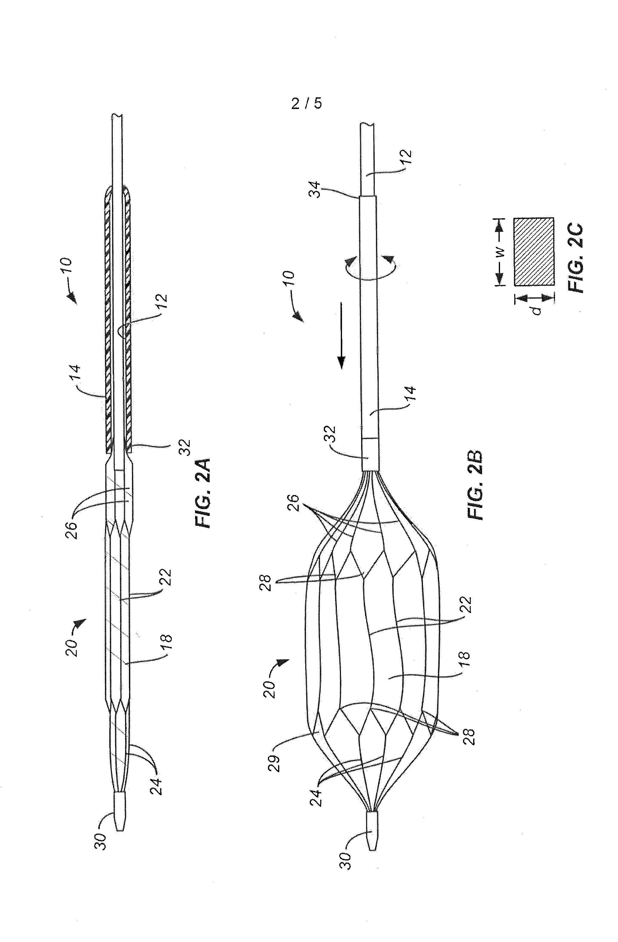
[0016]In an exemplary embodiment, the elastic metal cage structure comprises a plurality of circumferentially arranged, axially elongated hexagonal cells, where each cell has a proximal connection point and a distal connection at longitudinally opposed ends of the cell. Axial struts are connected to each of the connection points, and the struts are used to connect the cage structure to the catheter shaft. At the distal end, the axial struts are connected directly to the catheter shaft. In contrast, at the proximal end, the axial struts are connected to a compliance tube, where the compliance tube is disposed coaxially over the catheter shaft and attached to the catheter shaft only at a proximal end of the compliance tube. The axial connector links at the proximal end of the elastic metal cage structure are attached to a distal end of the compliance tube. In this way, the compliance tube can accommodate both axial foreshortening of the cage as the balloon is radially expanded as well as to accommodate any rotational, torsional forces experienced by the cage structure as the balloon is expanded.

Problems solved by technology

Such stenotic valves become stiff such that functioning of the valve leaflets deteriorates, including a reduced opening of the leaflets available to allow blood flow during ventricular systole.

Method used


Image

  • Method and system for treating valve stenosis
  • Method and system for treating valve stenosis
  • Method and system for treating valve stenosis

Examples


Embodiment Construction

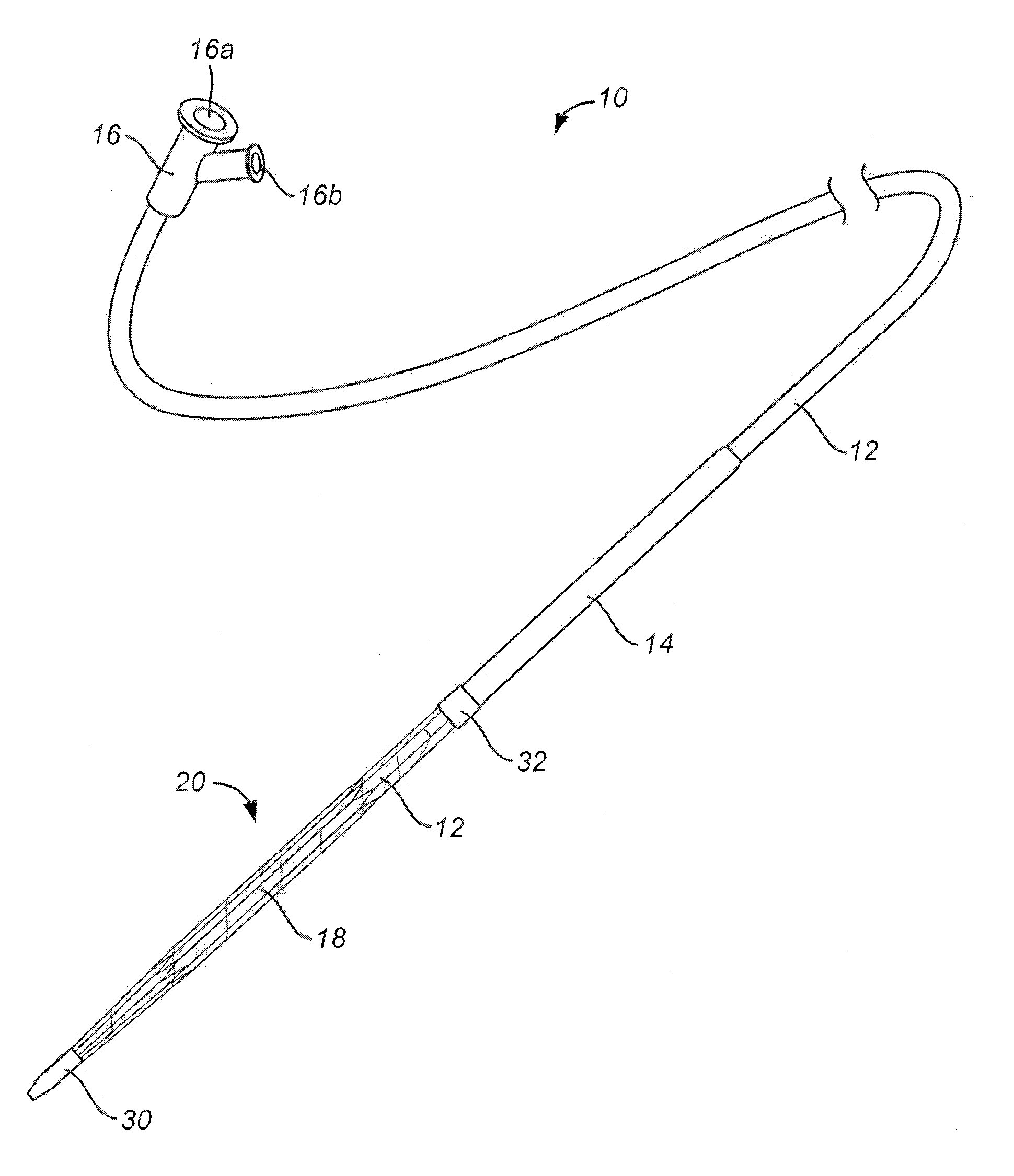
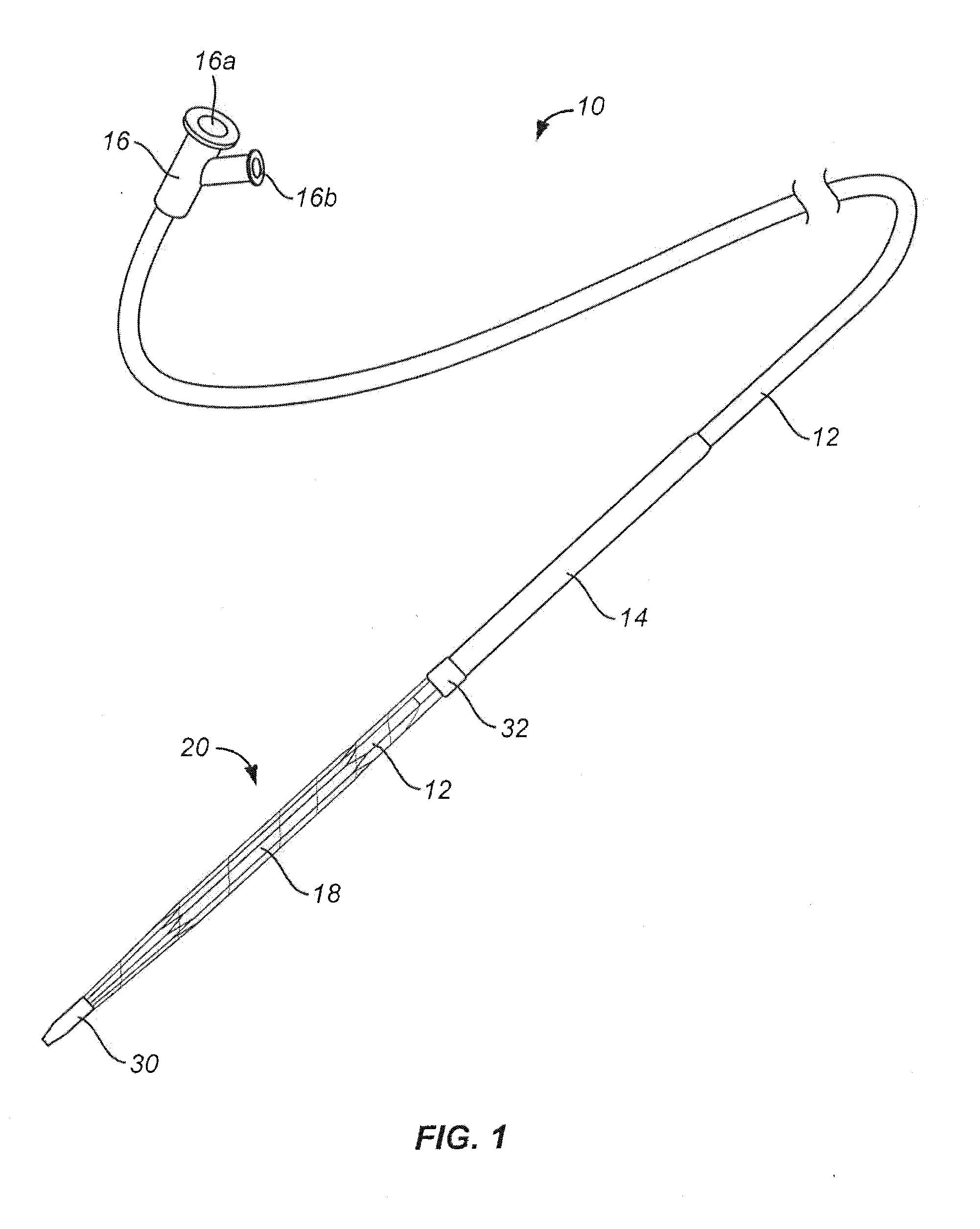
[0023]A valvuloplasty catheter 10 constructed in accordance with the principals of the present invention is illustrated in FIGS. 1, 2A, and 2B. The valvuloplasty catheter 10 comprises a shaft 12 having a compliance tube 14 coaxially disposed over a distal portion thereof. A proximal hub 16 includes an axial guide wire port 16a and a side balloon inflation port 16b. The guide wire port 16a attaches to a guide wire lumen which extends axially over the entire length of catheter shaft 12. The balloon inflation port 16b connects to an inflation lumen, typically formed in a wall of the shaft 12.

[0024]An expansible shell 18 is located at the distal end of the catheter shaft 12 and connected to receive inflation medium from the inflation lumen in the shaft which is connected to port 16b. In this way, the balloon can be inflated from a contracted or non-inflated configuration, as shown in FIG. 2A, to a fully inflated configuration, as shown in FIG. 2B.

[0025]An expansible metal cage 20 is mou...


PUM


Abstract

A valvuloplasty catheter comprises a balloon or other expansible shell which carries a plurality of scoring elements, typically formed in an elastic, self-closing metal cage. The expansible shell and scoring elements are positioned inside an aortic or other cardiac valve, and the shell expanded to engage the scoring elements against stenotic material which covers the valve leaflets and valve annulus. The scoring elements uniformly distributed force to break up the stenotic material, and the cage further contributes to rapid balloon deflation allowing shortening of the treatment time.

Description

CROSS REFERENCE TO RELATED APPLICATIONS[0001]This application is a divisional of co-pending U.S. patent application Ser. No. 13 / 236,449 filed on Sep. 19, 2011, which claims the benefit under 35 U.S.C. 119 of U.S. Provisional Patent Application No. 61 / 384,800, filed Sep. 21, 2010, the full disclosures of which are incorporated herein by reference.BACKGROUND OF THE INVENTION[0002]1. Field of the Invention[0003]The present invention relates generally to medical devices and methods. More particularly, the present invention relates to the use of an expandable scoring cage for disrupting stenotic deposits in cardiac valves.[0004]Stenosis of the aortic and other cardiac valves occurs when the valve annulus narrows restricting the flow of blood through the valve when open. This is a particular problem with aortic valve stenosis where the flow of oxygenated blood from the left ventricle to the rest of the body is limited. When the aortic valve is obstructed, the heart must pump at a higher p...

Claims


Application Information

Patent Timeline
Patent Type & Authority Applications(United States)
IPC IPC(8): A61B17/3207A61M25/10
CPCA61B17/320725A61B17/3207A61B2017/22098A61B2017/22061A61B2017/320008
Inventor GERSHONY, GARYDOTY, DAVID
Owner SPECTRANETICS
Learn More