Refrigeration cycle apparatus and outdoor heat source unit

Active Publication Date: 2013-10-03
MITSUBISHI ELECTRIC CORP
View PDF12 Cites 7 Cited by
  • Summary
  • Abstract
  • Description
  • Claims
  • Application Information

AI Technical Summary

Benefits of technology

The present invention aims to improve the efficiency of a refrigeration cycle apparatus during exhaust-heat recovery operations. The technical effect is to achieve better performance for the refrigeration cycle apparatus during exhaust-heat recovery.

Problems solved by technology

The inverter device is constituted by a plurality of switching elements, and because a high voltage and a large current flow through the switching elements, a heat loss occurs.
Therefore, there has been a problem in that the operation efficiency is degraded by the power input to the fan.

Method used


Image

  • Refrigeration cycle apparatus and outdoor heat source unit
  • Refrigeration cycle apparatus and outdoor heat source unit
  • Refrigeration cycle apparatus and outdoor heat source unit

Examples


first embodiment

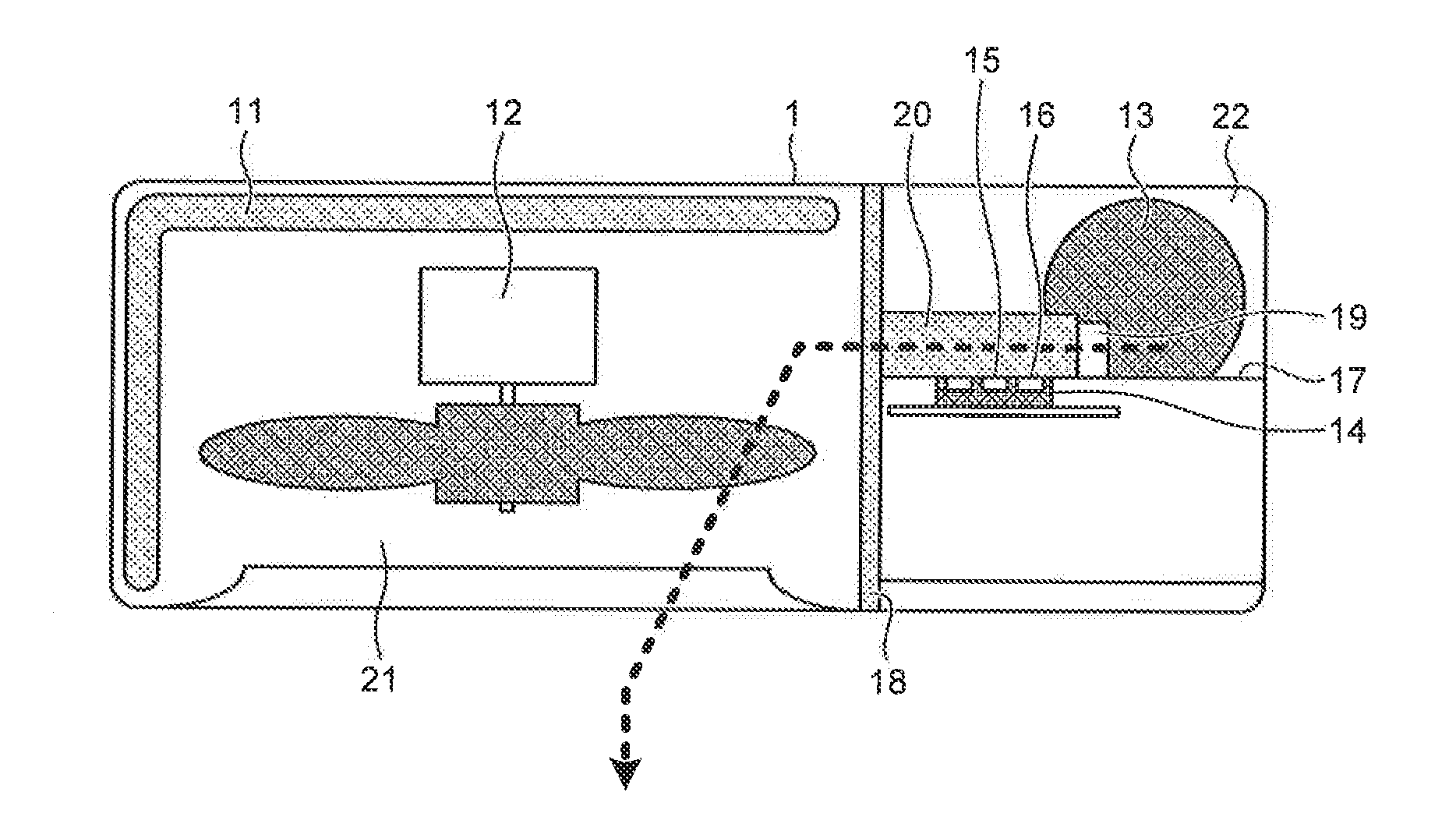
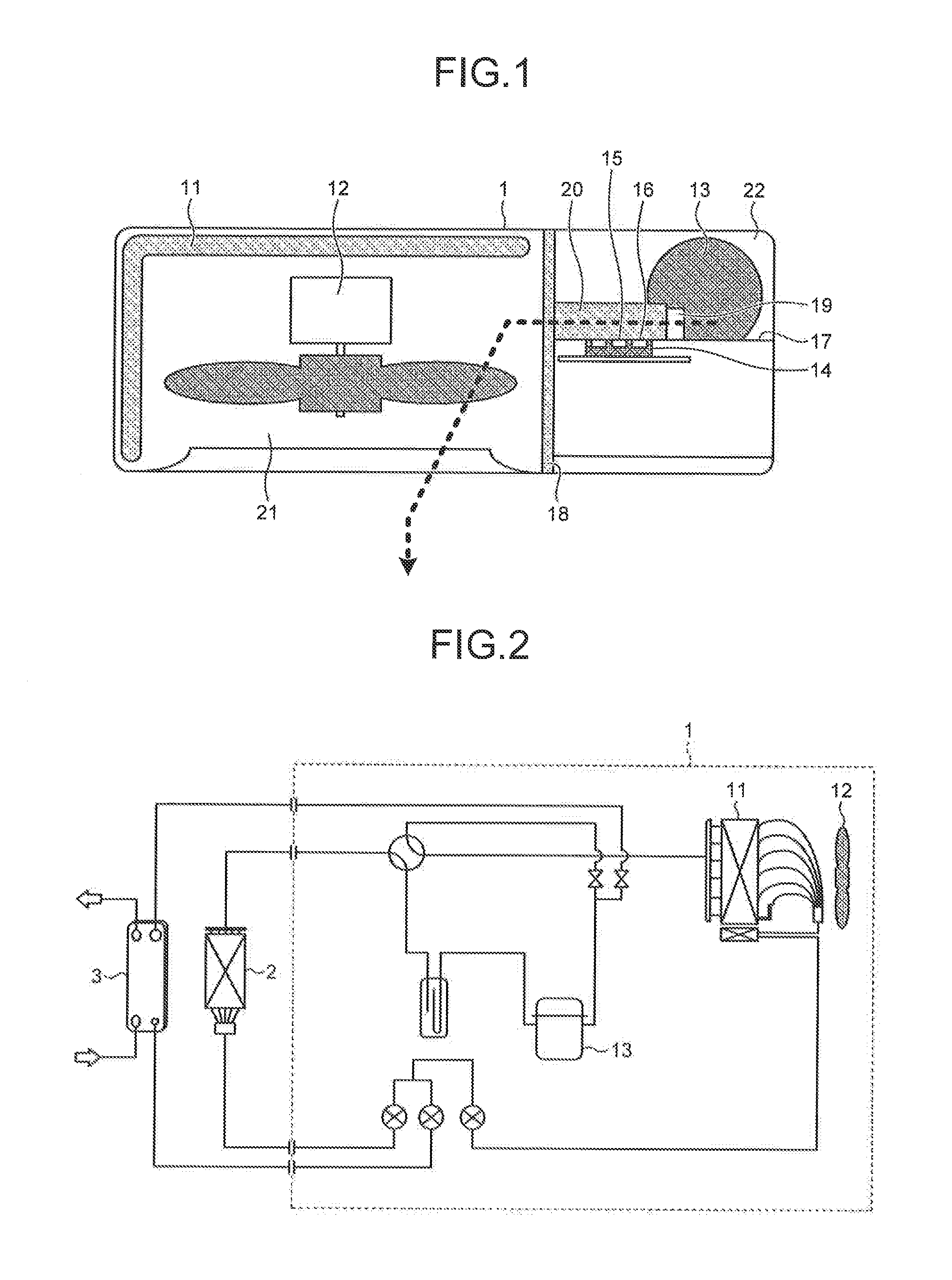
[0020]FIG. 1 is a configuration example of an outdoor heat source unit that is included in a refrigeration cycle apparatus according to a first embodiment of the present invention. An outdoor heat source unit 1 includes a refrigerant air-heat exchanger 11, a fan 12, a compressor 13, an inverter device 14 for driving the compressor 13, a switching element 15 in the inverter device 14, a temperature detection unit 16 in the inverter device 14, control device 17 that is an electric part including the inverter device 14, a separator sheet metal 18, a heat sink 19, and a sheet metal duct 20.

[0021]In the first embodiment, the switching element 15 in the inverter device 14 is constituted by a wide baudgap semiconductor made of a material such as SIC (silicon carbide) or GaN (gallium nitride). As the material of the wide bandgap semiconductor, besides SiC or a GaN based material, diamond and the like can be used.

[0022]The outdoor heat source unit 1 is divided by the separator sheet metal 18...

second embodiment

[0035]FIG. 5 is a configuration example of an outdoor heat source unit according to a second embodiment of the present invention. An outdoor heat source unit 1a includes the refrigerant air-heat exchanger 11, the fan 12, the compressor 13, the inverter device 14 for driving the compressor 13, the switching element 15 in the inverter device 14, the temperature detection unit 16 in the inverter device 14, a control device 17a that is an electric part including the inverter device 14, a separator sheet metal lea, and a heat sink 19a. Similarly to the first embodiment, the switching element 15 in the inverter device 14 is constituted by a wide bandgap semiconductor made of a material such as SiC or GaN.

[0036]The outdoor heat source unit 1a is divided by the separator sheet metal 18a to form a fan cabin 21a and a machine cabin 22a. In the fan cabin 21a, the refrigerant air-heat exchanger 11, the fan 12, and the heat sink 19a are arranged. In the machine cabin 22a, the compressor 13, the ...


PUM


Abstract

There is provided a refrigeration cycle apparatus in which an outdoor heat source unit, an indoor unit, and a water heating unit are connected, and an air conditioning operation and a water heating operation can be performed separately, and an exhaust-heat recovery operation can be performed by simultaneously performing air cooling and water heating. The outdoor heat source unit includes a compressor for compressing refrigerant, a refrigerant air-heat exchanger that performs heat exchange between the refrigerant and outside air, a fan for cooling the refrigerant air-heat exchanger, a control device that includes an inverter device for driving the compressor, and a heat sink for dissipating heat of the inverter device, and a switching element in the inverter device is constituted by an element formed by a wide bandgap semiconductor.

Description

BACKGROUND OF THE INVENTION[0001]1. Field of the Invention[0002]The present invention relates to a refrigeration cycle apparatus in which an exhaust-heat recovery operation can be performed by simultaneously operating air cooling and water heating.[0003]2. Description of the Related Art[0004]Conventionally, there is a type of refrigeration cycle apparatus that includes an outdoor heat source unit and a refrigerant circuit formed by connecting an indoor unit and a water heating unit by piping. The refrigeration cycle apparatus is capable of operating air cooling and water heating separately in a single system, and also capable of operating air cooling and water heating simultaneously (see, for example, Japanese Patent Application Laid-open No. 2010-196950). In this system, exhaust heat generated at the time of air cooling can be recovered for water heating by simultaneously performing an air cooling operation and water heating. Thus, a highly efficient operation can be achieved.[0005...

Claims


Application Information

Patent Timeline
IPC IPC(8): F25B29/00
CPCF25B29/003F25B31/006Y02B30/741F25B2600/11F25B2600/021F24F1/24Y02B30/70Y02P80/15F24D3/18F24F5/00F25B27/02F25B49/02F25B2600/111F25B2700/2103F25B2700/21153F25B2700/21154
Inventor AMANO, KATSUYUKI
Owner MITSUBISHI ELECTRIC CORP
Why Eureka
Try Eureka