Information Handling System Thermal Control By Energy Conservation

a technology of information handling system and energy conservation, applied in the direction of electrical apparatus enclosures/cabinets/drawers, electrical apparatus construction details, instruments, etc., can solve the problems of high stress operating conditions that exceed the capabilities of the chassis cooling system, and the temperature of the enclosure is not always accurate, so as to reduce the temperature of the cooling airflow, the effect of accurate measuremen

Active Publication Date: 2013-10-03
DELL PROD LP
View PDF7 Cites 51 Cited by
  • Summary
  • Abstract
  • Description
  • Claims
  • Application Information

AI Technical Summary

Benefits of technology

[0010]In accordance with the present invention, a system and method are provided which substantially reduce the disadvantages and problems associated with previous methods and systems for managing cooling system operation and component throttling to manage thermal conditions of components that lack thermal monitoring. A thermal state at a predetermined location within a chassis enclosure is managed by applying power dissipation of electronic components and inlet temperature of a cooling airflow to set a fan speed that establishes a desired cooling airflow rate.
[0012]The present invention provides a number of important technical advantages. One example of an important technical advantage is that thermal conditions within an information handling system enclosure are accurately measured without having to dispose an array of sensors throughout the enclosure. Measurements of enclosure thermal conditions estimated by the Law of Conservation of Energy are applied to provide thermal control for downstream components that lack thermal sensors. If thermal conditions within the enclosure exceed a threshold associated with operation of unmonitored components, the thermal conditions are managed to maintain an operating environment acceptable to the unmonitored components. For example, upstream components are throttled to reduce thermal energy released to a cooling airflow, fan speed is increased to reduce cooling airflow temperature or unmonitored components are throttled or powered down to reduce downstream thermal energy release or prevent damage to the unmonitored components. Bulk enclosure thermal energy estimates derived from the Law of Conservation of Energy combined with thermal measurements from monitored components offers a more precise overall picture of thermal operating conditions at an information handling system without unnecessary thermal sensors and system complexity.

Problems solved by technology

One difficulty with management of thermal conditions in an information handling system chassis is that thermal conditions tend to vary throughout a chassis enclosure.
One difficulty with managing thermal conditions in an information handling system chassis enclosure is that not all components integrate thermal self-protection capabilities in order to maintain reliability conformance during thermal excursions, such as when a cooling system fails, extreme ambient environmental temperatures exist or ultra-high stress operating conditions exist that exceed the capabilities of a chassis' cooling system.
For example, a processor operating in extreme thermal conditions will throttle its power consumption to reduce heat generation and maintain its internal temperature within a desired constraint; however, mezzanine cards, some hard disk drives and many on board devices like networking, chipset, power distribution and BMC devices, do not include thermal sensors or thermal self-protection capabilities.
Unfortunately, if components do not have thermal sensors then no direct measurement of thermal conditions at the components exists to provide direct control over thermal conditions at the component.
Unfortunately, as air flows through an information handling system enclosure, air streamlines across the enclosure can have significant variation in temperature even across small linear separations.
This solution tends to increase system cost by the addition of plural interfaced sensors and system complexity by having multiple thermal measurements and multiple failure points.

Method used


Image

  • Information Handling System Thermal Control By Energy Conservation
  • Information Handling System Thermal Control By Energy Conservation
  • Information Handling System Thermal Control By Energy Conservation

Examples


Embodiment Construction

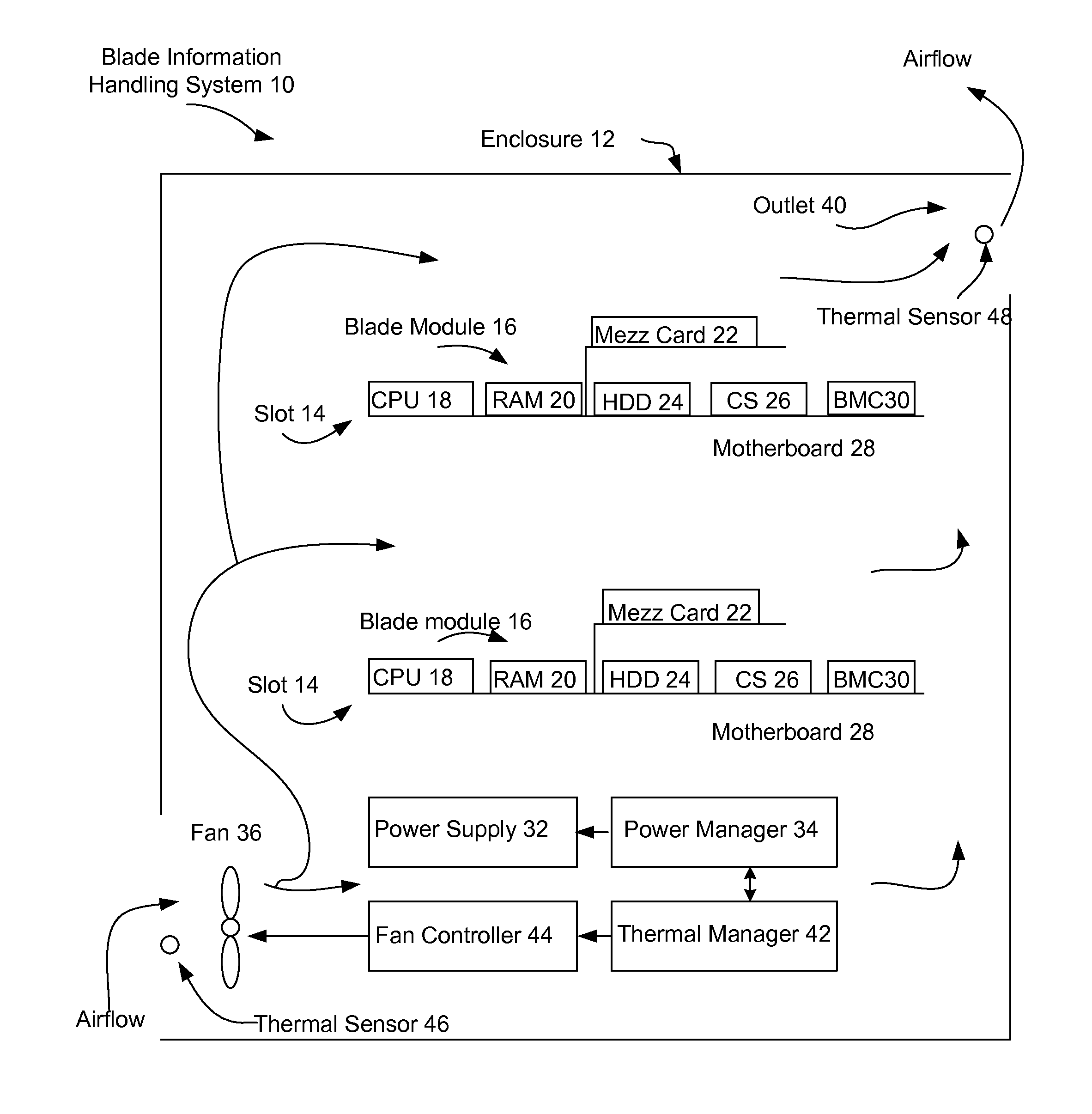
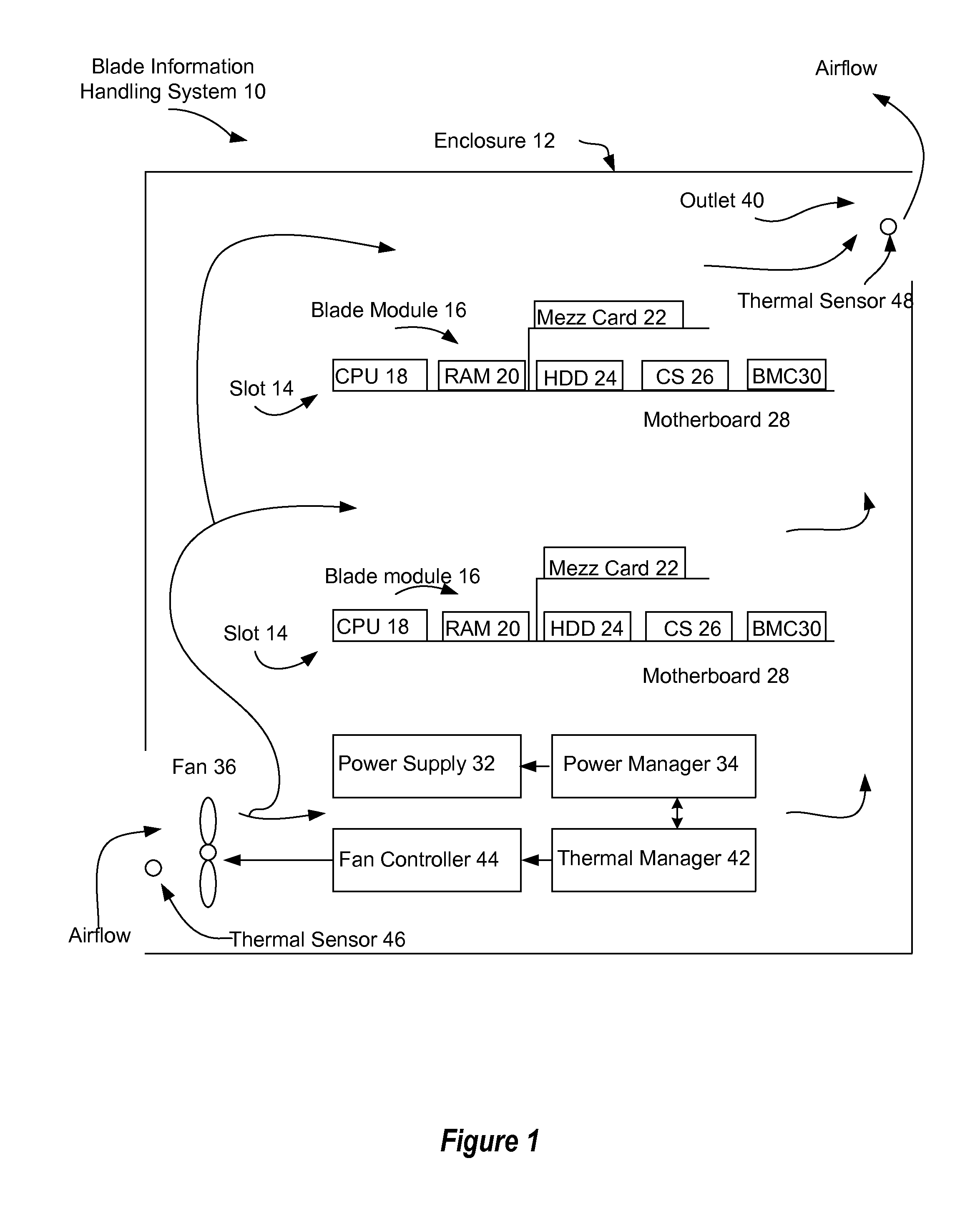
[0017]A thermal state within an information handling system enclosure is managed by adjusting fan speed for a cooling airflow in the enclosure based upon an inlet temperature of the cooling airflow and power dissipated to components running within the enclosure. For purposes of this disclosure, an information handling system may include any instrumentality or aggregate of instrumentalities operable to compute, classify, process, transmit, receive, retrieve, originate, switch, store, display, manifest, detect, record, reproduce, handle, or utilize any form of information, intelligence, or data for business, scientific, control, or other purposes. For example, an information handling system may be a personal computer, a network storage device, or any other suitable device and may vary in size, shape, performance, functionality, and price. The information handling system may include random access memory (RAM), one or more processing resources such as a central processing unit (CPU) or ...


PUM


Abstract

A thermal state within an information handling system enclosure is managed within predetermined constraints by estimating thermal energy introduced to the enclosure by power dissipation to electronic components and thermal energy removed from the enclosure by a cooling airflow generated by a fan. A desired bulk temperature of a cooling airflow is attained at a predetermined position in an enclosure by selecting a fan speed and power allocation to the components that conserves energy within the enclosure at a predetermined thermal state.

Description

BACKGROUND OF THE INVENTION[0001]1. Field of the Invention[0002]The present invention relates in general to the field of information handling system thermal control, and more particularly to information handling system thermal control by energy conservation.[0003]2. Description of the Related Art[0004]As the value and use of information continues to increase, individuals and businesses seek additional ways to process and store information. One option available to users is information handling systems. An information handling system generally processes, compiles, stores, and / or communicates information or data for business, personal, or other purposes thereby allowing users to take advantage of the value of the information. Because technology and information handling needs and requirements vary between different users or applications, information handling systems may also vary regarding what information is handled, how the information is handled, how much information is processed, st...

Claims


Application Information

Patent Timeline
Patent Type & Authority Applications(United States)
IPC IPC(8): G06F1/20
CPCY02B60/1275H05K7/20836H05K7/20727G06F1/206Y02D10/00G05D23/1927
Inventor SHELNUTT, AUSTINFLOREZ-LARRAHONDO, GERMANPARTHASARATHY, SHARADHADUNCAN, TYLER
Owner DELL PROD LP
Why Eureka
Try Eureka