Aircraft monument integrated attachment device

a monument and integrated technology, applied in the direction of aircraft crew accommodation, rod connection, transportation and packaging, etc., can solve the problems of adding weight to the aircraft, and monument attachments that cannot be moved to a new location

Active Publication Date: 2013-10-03
BE AEROSPACE INCORPORATED
View PDF10 Cites 25 Cited by
  • Summary
  • Abstract
  • Description
  • Claims
  • Application Information

AI Technical Summary

Benefits of technology

[0008]The floor fitting can be pre-manufactured from aluminum, titanium, a reinforced, hardened plastic or carbon fiber, and either be machined, cast or injection molded depending on the calculated strength requirements and / or advances in material capabilities. An advantage of the present invention is that the fitting still allows X, Y and Z adjustment at monument installation but without significantly increasing inward floor fitting projection and without additional projection outside the galley envelope.
[0009]The fitting may be manufactured to accommodate either single or twin bolt fixings as primary attachments. A low load flutter point or stabilizer fitting could also use the same manufacturing and bonding principles with the required limit on X, Y, or Z movement provisioned for.

Problems solved by technology

These fittings do not allow relocation of the monuments to a new location, unless seat track mountings are used that allow either fore and aft movement, or lateral movement, along the track depending upon the orientation of the track.
However, a full range of motion is typically unavailable for monument attachments in an aircraft.
Where variations exist in the position of the monument, or the position of the hard point attachments or seat tracks, the floor fitting has to be installed in that specific location during manufacture, and relocation or repositioning is limited and every orientation, change in monument location or change in foot print size requires a new location for the floor attachments as part of the structure.
The existing monument attachment design leads to a bias stress loading to one skin of the composite panel, which often fails to optimize the load path into the structure and can lead to a requirement for additional reinforcement in the form of a metallic plate or “doubler” to help spread the stress more effectively throughout the monument and avoid stress concentrations.
Unfortunately, this not only adds weight to the aircraft, but is an inefficient means to distribute the load.
This, in turn, does not allow standardization of cart bay doors, except for the widest possible dimension.
Additionally, with chilled or refrigerated galleys the presence of a sizable metallic component projecting through the cart bay wall produces significant undesirable cold bridges that can compromise the integrity of the chilled compartment, from a thermal resistance point of view, and the result is a failure to maintain the specified compartment temperature for maintaining perishable food stuffs during normal aircraft operations.

Method used


Image

  • Aircraft monument integrated attachment device
  • Aircraft monument integrated attachment device
  • Aircraft monument integrated attachment device

Examples


Embodiment Construction

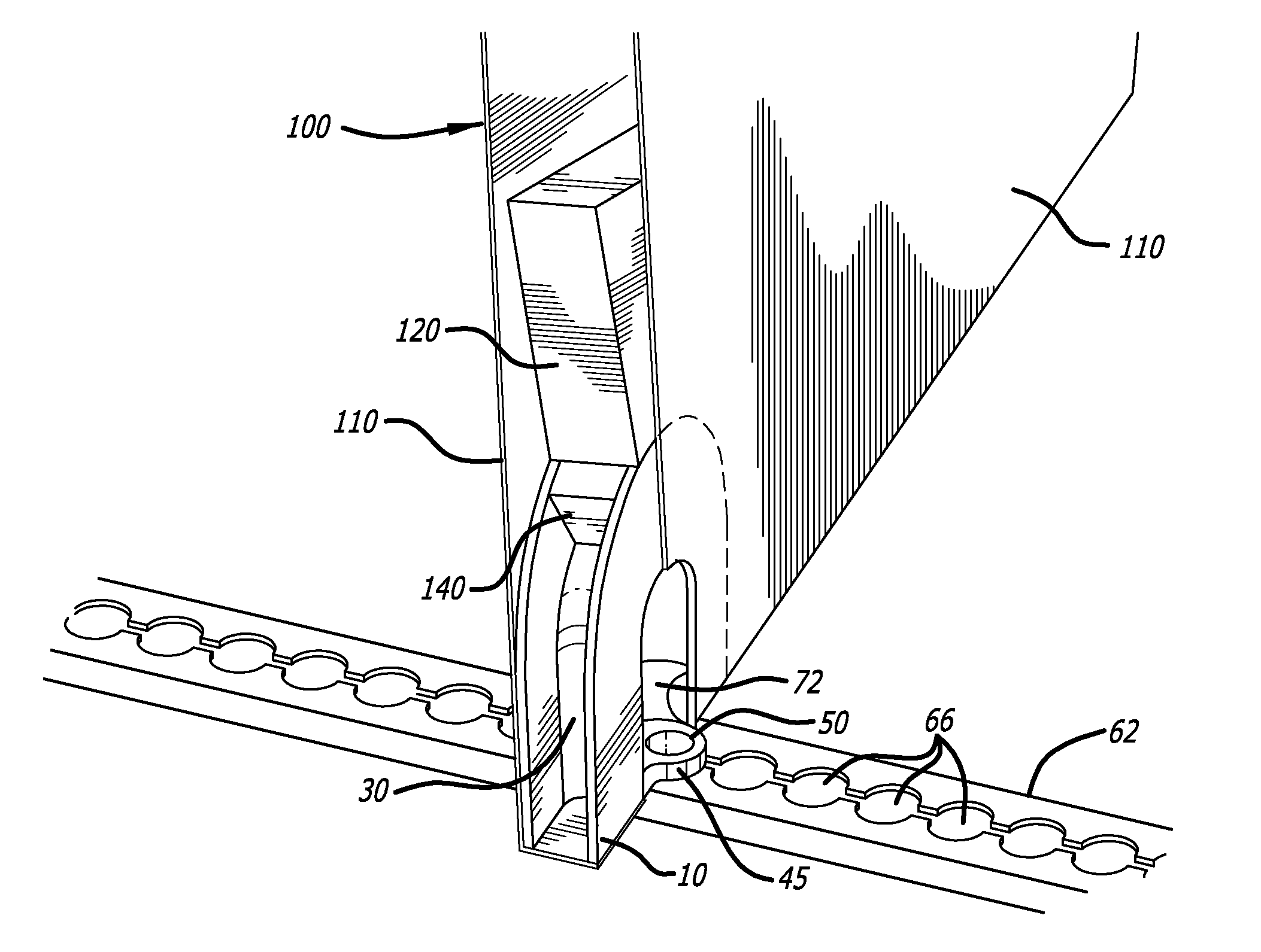
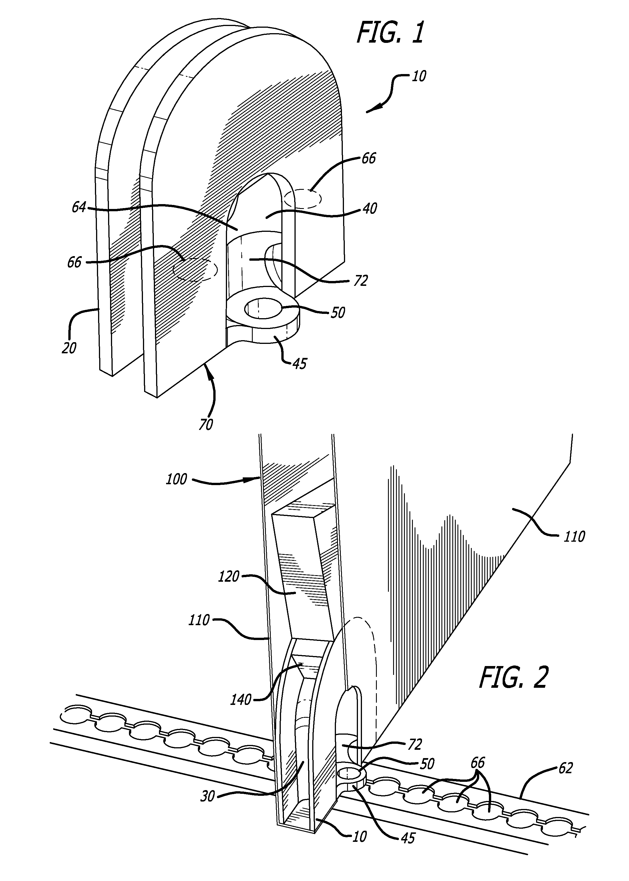
[0014]FIG. 1 illustrates a first embodiment of a monument attachment device according to the present invention. The attachment device 10 comprises two horseshoe shaped plates 20 having an outer radius along the perimeter and an inner radius along the inner edge. The two plates 20 are joined together along the inner radius by a rigid panel 30, such that there is an arcuate gap between the two plates 20, and between the rigid panel 30 and the outer radius of the two plates 20. The connection of the two plates to the rigid panel 30, such as by welding or as a one piece casting or molding, for example, is sufficient to transfer loads from the panel 30 to the plates 20.

[0015]At the base of the attachment device 10 is a block 40 including a pair of lugs 45 formed in the block 40 to secure to the fitting to an attachment point on the aircraft. Each lug 45 includes a through hole 50 for receiving a fastener that fixes the block 40 and attachment device 10 to a transversely oriented rail 62 ...


PUM


Abstract

An attachment device for an aircraft monument is disclosed having a pair of spaced apart parallel plates having vertical sides and a rounded upper surface defining an arch. A panel attaches the spaced apart parallel plates along an inner radius, and a pair of lugs including a vertical channel is disposed below the plates for receiving fasteners to connect the attachment device to a rail or planar surface.

Description

CROSS-REFERENCES TO RELATED APPLICATIONS[0001]This application claims priority from U.S. application Ser. No. 61 / 616,952, filed Mar. 28, 2012, the contents of which are incorporated herein by reference in its entirety.BACKGROUND[0002]Aircraft interior space is made up of various compartments, such as galleys, crew cabins, stowages, closets, lavatories, crew rest quarters, and other facility and storage monuments. These compartments of typically formed by partitions or structural units that separate one compartment from another. To meet airworthiness requirements on commercial passenger-carrying aircraft for the retention of compartments such as galleys attachment or connection devices must be used to secure them to the aircraft's airframe structure. Commonly, these take two forms: type one securing the lower section of the monument to the floor; and type two securing the upper section to the ceiling. Common practice is to manufacture these parts from a combination of aluminum, stain...

Claims


Application Information

Patent Timeline
Patent Type & Authority Applications(United States)
IPC IPC(8): F16B9/02
CPCB64D11/04F16B9/026B64D11/02Y10T403/39B64D2011/0046Y02T50/46B64D11/0696B64D11/00Y02T50/40F16B9/02B64C1/00B64D2011/0069
Inventor BURD, PETER JOHN LESLIE
Owner BE AEROSPACE INCORPORATED
Why Eureka
Try Eureka