Stretchable electrical interconnect and method of making same

Active Publication Date: 2013-10-10
THE HONG KONG RES INST OF TEXTILES & APPAREL
View PDF12 Cites 4 Cited by
  • Summary
  • Abstract
  • Description
  • Claims
  • Application Information

AI Technical Summary

Benefits of technology

[0036]Advantageously, in the present invention the at least one conductive fibre is configured to form a stretchable interlaced configuration, for instance a knitted configuration, in which the at least one conductive fibre forms interlaced loops which are not bonded to an elastic substrate. Accordingly, the interlaced loops are free to slide and change their geometries within the structure of the stretchable interlaced configuration which may assist in maintaining the electrical properties when repeatedly flexed and stretched around three-dimensional curvilinear surfaces. In contrast, traditional approaches involve electrical interconnects being adhesively bonded to separate rubber or silicone-like substrates with curved shapes. In the existing art, the stretchability is limited by bonding integration which may easily cause stress concentration in the crest and trough parts of the elastic substrate.
[0037]Other advantages of the present invention includes that it involves a relatively simple structure, is relatively light weight and is relatively easy and cost-effective to fabricate using existing technologies. Furthermore, due to the interlaced integration between the electrically conductive fibres and the elastic fibres, the electrically conductive fibres have greater freedom to move and this alleviates stress concentration in the crest and trough parts of the knitted loops of the electrical intercon

Problems solved by technology

However, adhesive fractures tend to develop between the metal conductive films of the electrical interconnect and the elastic substrate due to flexing and stretching, and this can result in short-circuiting and subsequent electrical failure of the electrical interconnect.
However, the conductivity of these composites is not yet as high as metals.
Furthermore, existing electrical interconnect structures ar

Method used


Image

  • Stretchable electrical interconnect and method of making same
  • Stretchable electrical interconnect and method of making same
  • Stretchable electrical interconnect and method of making same

Examples


Embodiment Construction

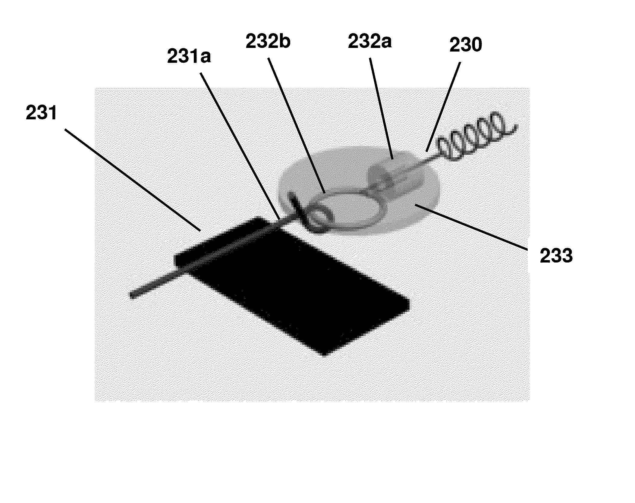
[0063]A first embodiment of the present invention will now be described herein with reference to FIGS. 1 to 21 in which a flexible and stretchable electrical interconnect is integrally formed by knitting a conductive copper wire with a plurality of elastic polyester fibres and Spandex filaments. A further embodiment of the present invention is also described with reference to FIGS. 22 and 23 in which a coupling interface is provided for coupling an electrical component such as a sensor to the electrical interconnect.

[0064]Traditional technologies adopt an approach in which electrical interconnects are adhesively bonded to separate rubber or silicone-like substrates with curved shapes. In the existing art, the stretchability is limited by bonding integration which may easily cause stress concentration in the crest and trough parts of the elastic substrate.

[0065]In contrast, the embodiments of the present invention are suitable for application in electronic garments and the like due t...


PUM

PropertyMeasurementUnit
Diameteraaaaaaaaaa
Diameteraaaaaaaaaa
Electrical conductoraaaaaaaaaa

Abstract

An electrical interconnect including at least one electrically-conductive fibre configured to form a stretchable interlaced configuration.

Description

TECHNICAL FIELD[0001]The present invention relates to the field of stretchable electrical interconnects suitable for used in garments and the like, and methods of making same.BACKGROUND OF THE INVENTION[0002]There is a perceived demand for wearable electrical interconnects (also referred to as “circuit matrices”) capable of carrying current or transporting charge in electrical systems which are suitably flexible and stretchable so as to contour to three-dimensional curvilinear surfaces of the human body in such applications as electronic garments, flexible displays, electronic artificial skins, and personal health assistants.[0003]Typically, stretchable electrical interconnects are created by depositing and bonding the metal conductive films of the electrical interconnect on to rubber-like elastic substrates typically having out-of-plane wavy patterns or in-plane tortuous patterns. The elastic substrates are designed to provide some degree of flexing and stretching of the electrical...

Claims


Application Information

Patent Timeline
IPC IPC(8): A41D1/00H01R43/00H01R43/16H01B5/08H01B5/16
CPCD02G3/441D04B1/18Y10T29/49204Y10T29/49169D10B2403/02431
Inventor TAO, XIAOMINGLI, QIAOZHU, BO
Owner THE HONG KONG RES INST OF TEXTILES & APPAREL
Why Eureka
Try Eureka