Steam condensation tower for a granulation installation

a technology of granulation installation and steam condensation tower, which is applied in the direction of manufacturing tools, lighting and heating equipment, furniture, etc., can solve the problems of cyclic production of molten materials in metallurgical processes, low steam condensation capacity, and inability to handle the full steam flow, so as to achieve more reliable evacuation and low additional cost

Active Publication Date: 2013-10-10
PAUL WURTH SA
View PDF3 Cites 9 Cited by
  • Summary
  • Abstract
  • Description
  • Claims
  • Application Information

AI Technical Summary

Benefits of technology

[0006]A steam condensation tower is herein provided, which enables more reliable evacuation of excessive steam during granulation at peak flow rates, while being compatible with existing granulation plant designs at comparatively low additional cost.

Problems solved by technology

In fact, due to the high temperatures of the molten material and the huge amount of quenching water required, a considerable amount of steam is typically produced by installations according to FIG. 5.
Production of molten material in metallurgical processes is typically cyclic and subject to considerable fluctuations in terms of produced flow rates.
In order to find a suitable compromise between installation size and costs, the steam condensation capacity is often not designed to handle the full steam flow, which might be generated during peak slag flows.
However, observation has shown that in practice, such overpressure flaps do not always reliably open at excess melt flow rates.
Accordingly, excess steam remains inside the tower, and overpressure is subsequently generated.
Such reverse steam flow may lead, at the very least, to bad visibility in the casthouse, which is obviously a serious safety risk for operating personnel.
Much more adversely, steam blowing back through the internal hood can lead to considerable generation of low-density slag particles (so-called “popcorn”) when the steam comes into contact with the liquid hot melt inside the slag runner spout.
Such hot particles, when projected into the casthouse, generate an even more severe safety risk.

Method used


Image

  • Steam condensation tower for a granulation installation
  • Steam condensation tower for a granulation installation
  • Steam condensation tower for a granulation installation

Examples


first embodiment

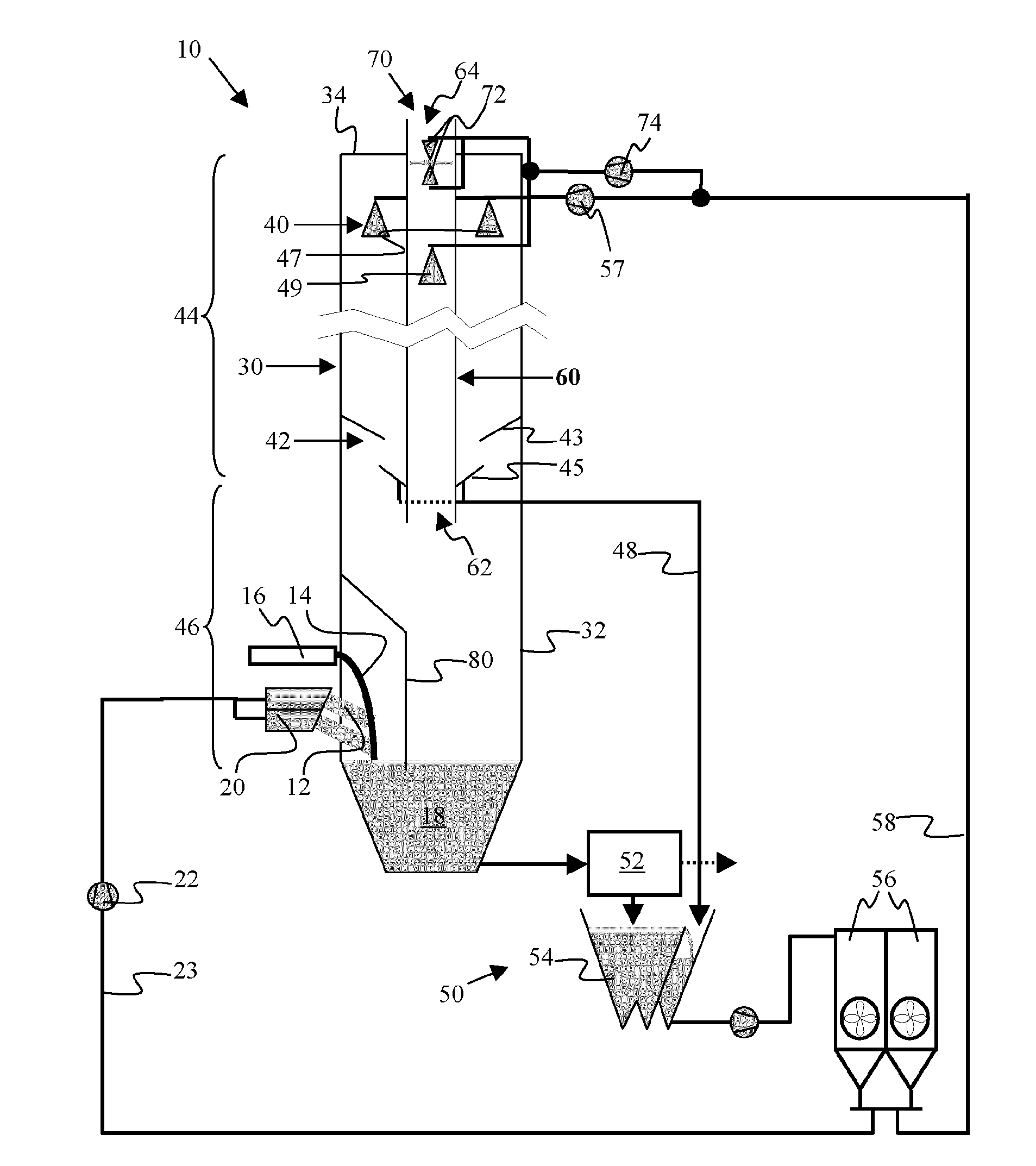
[0020]For illustrating the present invention, FIG. 1 shows a diagrammatic view of a granulation installation 10 designed for slag granulation in a blast furnace plant (the plant not being shown). Generally speaking, the installation 10 thus serves to granulate a flow of molten blast furnace slag 14 by quenching it with one or more jets 12 of comparatively cold granulation water. As seen in FIG. 1, a flow of molten slag 14, inevitably tapped with the pig iron from a blast furnace, falls from a hot melt runner tip 16 into a granulation tank 18. During operation, jets of granulation water 12, which are produced by a water injection device 20 (often also called a “blowing box”) supplied by one or more parallel high-pressure pump(s) 22, impinge onto the molten slag 14 falling from the hot runner tip 16. A suitable configuration of a water injection device 20 is described e.g. in patent application WO 2004 / 048617. In older granulation installations (not shown, but encompassed), molten sla...


PUM

PropertyMeasurementUnit
heightaaaaaaaaaa
heightaaaaaaaaaa
diametersaaaaaaaaaa

Abstract

A granulation installation for a melt produced in a metallurgical plant, especially for blast furnace slag having a water injection device for quenching and thereby granulating the melt and a granulation tank for collecting water and granulates a steam condensation tower is located above the granulation tank for collecting steam generated in the tank, where the tower has a steam condensing system with a water-spraying device and a water-collecting device below the water-spraying device, and the tower is equipped with a stack for selectively evacuating excessive steam to the atmosphere, the stack having an inlet communicating with the lower zone of the condensation tower and an outlet arranged to evacuate steam to the atmosphere above the condensation tower, the stack being equipped with an obturator device for selective evacuation of steam through the stack, where the installation according to the invention may process an increase of 60% of slag, e.g. around +5 t/min of slag in a system having a condensation capacity designed to handle a maximum slag flow rate of 8 t/min, without any risk of steam backflow in the granulation area.

Description

TECHNICAL FIELD[0001]The present invention generally relates to a granulation installation for molten material, especially for metallurgical melts such as blast furnace slag. It relates more particularly to an improved steam condensation tower design for use in such an installation.BACKGROUND ART[0002]An example of a modern granulation installation of this type, especially for molten blast furnace slag, is illustrated in appended FIG. 5 that is part of a paper entitled “INBA® Slag granulation system—Environmental process control” published in Iron&Steel Technology, issue April 2005. As seen in FIG. 5, this kind of installation typically comprises: a water injection device [2] (also called blowing box), for injecting granulation water into a flow of molten material, e.g. slag that is received via a runner tip [1]. Thereby, granulation of the molten material is achieved. The installation further has a granulation tank [3] for collecting the granulation water and the granulated materia...

Claims


Application Information

Patent Timeline
Patent Type & Authority Applications(United States)
IPC IPC(8): C21B3/06F27B1/10F28B3/04
CPCC21B3/06C21B3/08F28B3/04F27D15/02F27D15/0286F27B1/10C21B2400/062C21B2400/024C21B2400/074C21B2400/072
Inventor GREIVELDINGER, BOB
Owner PAUL WURTH SA
Why Eureka
Try Eureka