
Audio Communication System, An Audio Transmitter and An Audio Receiver

Inactive Publication Date: 2013-10-10
KTMICRO ELECTRONICS
View PDF10 Cites 9 Cited by
  • Summary
  • Abstract
  • Description
  • Claims
  • Application Information

AI Technical Summary

Benefits of technology

The patent text describes an audio communication system that improves the compression and expansion of audio signals to create a better match between the compressor at the transmitter and the expandor at the receiver. The use of digital compandor and processing has led to improved linearity and higher precision compared to analog processing. The adoption of digital processing not affected by manufacturing processes as much as analog processing also helps create a better match between the compressor and expandor.

Problems solved by technology

For the transmitting and receiving systems illustrated in FIG. 1A and FIG. 1B, the signal to noise ratio is limited by the FM portion of the transmitter, since the signal to noise ratio of voltage-controlled oscillator for the FM part of the transmitter is relatively low, generally below 70 dB, therefore, the signal to noise ratio for the transmitting and receiving system is generally poor.

Method used


Image

  • Audio Communication System, An Audio Transmitter and An Audio Receiver
  • Audio Communication System, An Audio Transmitter and An Audio Receiver
  • Audio Communication System, An Audio Transmitter and An Audio Receiver

Examples


Embodiment Construction

.”

BRIEF DESCRIPTION OF THE DRAWINGS

[0014]Features, aspects, and embodiments are described in conjunction with the attached drawings, in which:

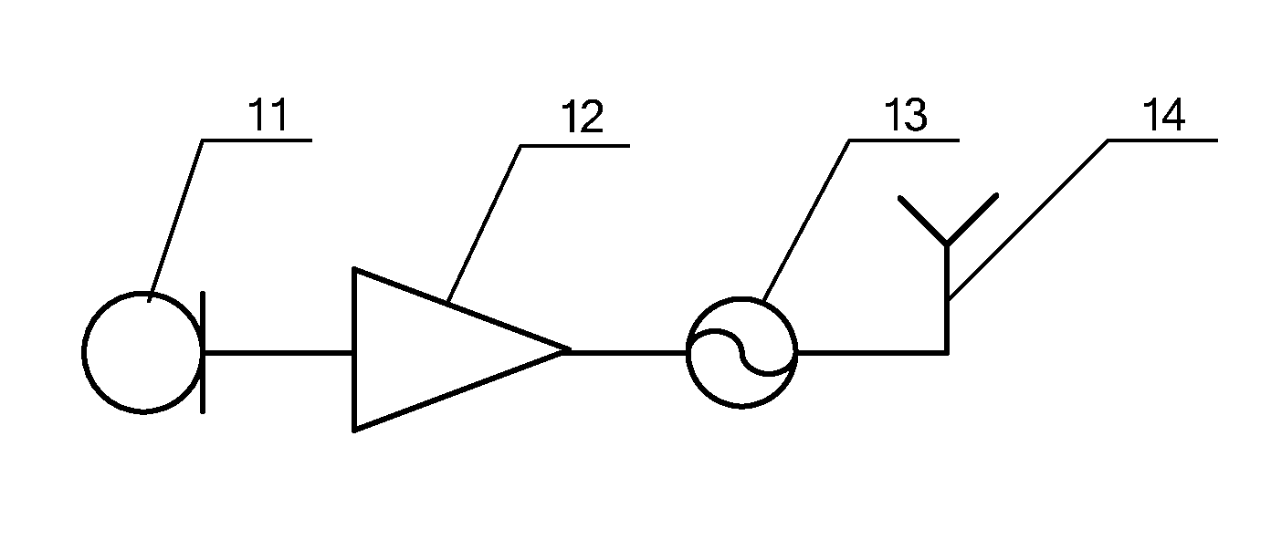
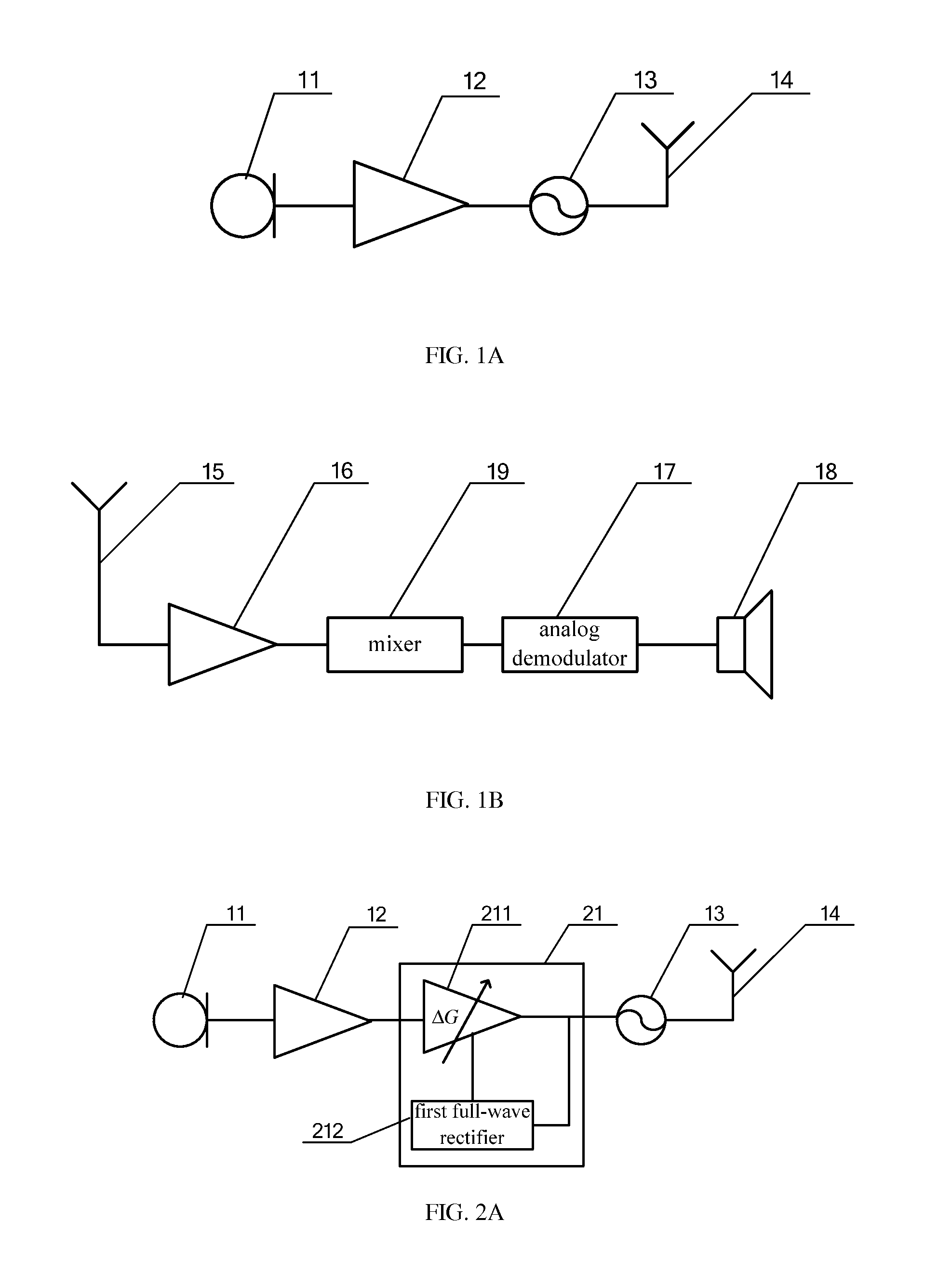
[0015]FIG. 1A is a schematic diagram showing a wireless microphone transmitter under the existing technologies;

[0016]FIG. 1B is a schematic diagram showing a wireless microphone receiver under the existing technologies;

[0017]FIG. 2A is a schematic diagram showing another wireless microphone transmitter under the existing technologies;

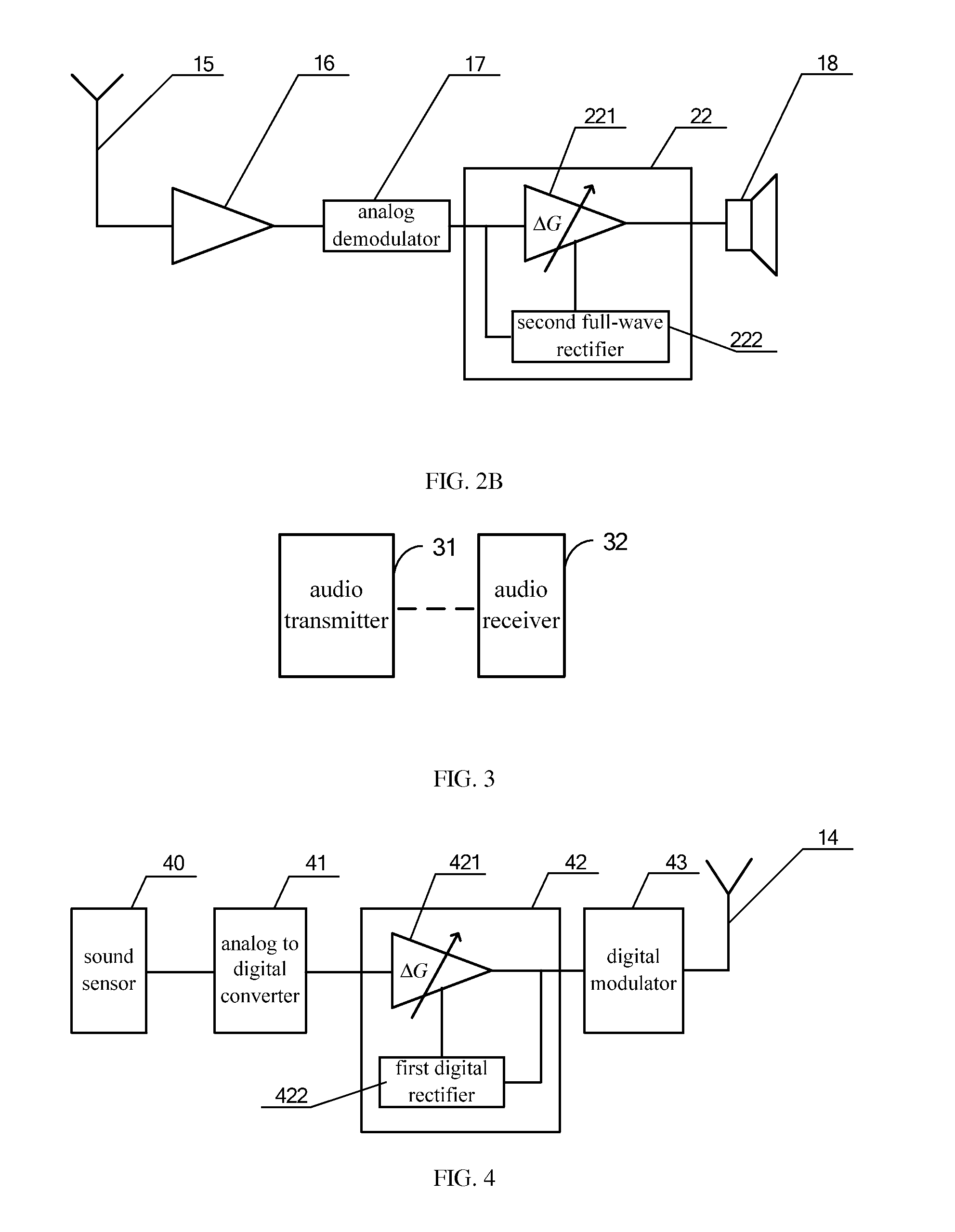
[0018]FIG. 2B is a schematic diagram showing another wireless microphone receiver under the existing technologies;

[0019]FIG. 3 is a schematic diagram showing an audio communication system according to one embodiment;

[0020]FIG. 4 is a schematic diagram showing an audio transmitter according to one embodiment;

[0021]FIG. 5 is a schematic diagram showing the working principle of the digital compressor in the audio transmitter according to one embodiment;

[0022]FIG. 6 is a schematic diagram showing an audio receiver acc...


PUM


Abstract

An audio communication system, an audio transmitter and an audio receiver are described herein. In one aspect, the audio transmitter includes: An analog to digital converter configured to convert an analog audio signal into a digital audio signal; a digital compressor configured to compress the dynamic range of said digital audio signal; a digital modulator configured to modulate the compressed digital audio signal into a wireless communication signal; and the analog to digital converter, the digital compressor and the digital modulator are integrated in one integrated circuit. The described devices improve the compression and expansion device linearity, resulting in better match for the compressor at the transmitter and the expandor at the receiver.

Description

RELATED APPLICATIONS INFORMATION[0001]The application claims priority under 35 U.S.C. 119(a) to Chinese application number 201220149419X, filed on Apr. 10, 2012, which is incorporated herein by reference in its entirety as if set forth in full.BACKGROUND[0002]1. Technical Field[0003]The embodiments described herein relate to microelectronics, and more specifically, to an audio communication system, an audio transmitter and an audio receiver.[0004]2. Related Art[0005]FIG. 1A is a schematic diagram showing a wireless microphone transmitter under the existing technologies. The wireless microphone transmitter includes a microphone 11, a first amplifier 12, an analog voltage controlled oscillator 13 and a transmitting antenna 14, the analog audio signal outputted by the microphone 11 is amplified by the first amplifier 12, the amplified analog audio signal is then converted by the analog voltage controlled oscillator 13 into an analog Frequency Modulation (FM) signal, the analog FM signa...

Claims


Application Information

Patent Timeline
IPC IPC(8): G10L19/00
CPCG10L19/00H04B1/16H04B1/04H04R2420/07H03G7/002H03G7/007
Inventor LI, XUFANGLI, ZHENXIANG, YIHAIYANG, PEIZHANG, FUBIN
Owner KTMICRO ELECTRONICS
Features
  • Generate Ideas
  • Intellectual Property
  • Life Sciences
  • Materials
  • Tech Scout
  • Unparalleled Data Quality
  • Higher Quality Content
  • 60% Fewer Hallucinations
Learn More