Isolated Voltage Transducer

Active Publication Date: 2013-10-17
MULTIDIMENSION TECH CO LTD
View PDF4 Cites 14 Cited by
  • Summary
  • Abstract
  • Description
  • Claims
  • Application Information

AI Technical Summary

Benefits of technology

[0032]The present invention measures the voltage across the load using a magnetic method. Because the measurement of magnetic field is electrically isolated from the load working circuits, there is no direct electrical connection between the integr

Problems solved by technology

Often these applications involve environments with hazardous voltages, transient signals, common-mode voltages, and fluctuating ground potentials capable of damaging electronic systems and in an extreme case, causing physical harm to a person in contact with the electronic device.
Without the use of an encoding technique, such as a voltage to frequency converter on the input side of the circuit, capacitor and transformer based techniques are limited to AC signals.
Transformers are relatively expensive and difficult to build into an integrated circuit while maintaining high sensitivity and low frequency performan

Method used


Image

  • Isolated Voltage Transducer
  • Isolated Voltage Transducer
  • Isolated Voltage Transducer

Examples


Example

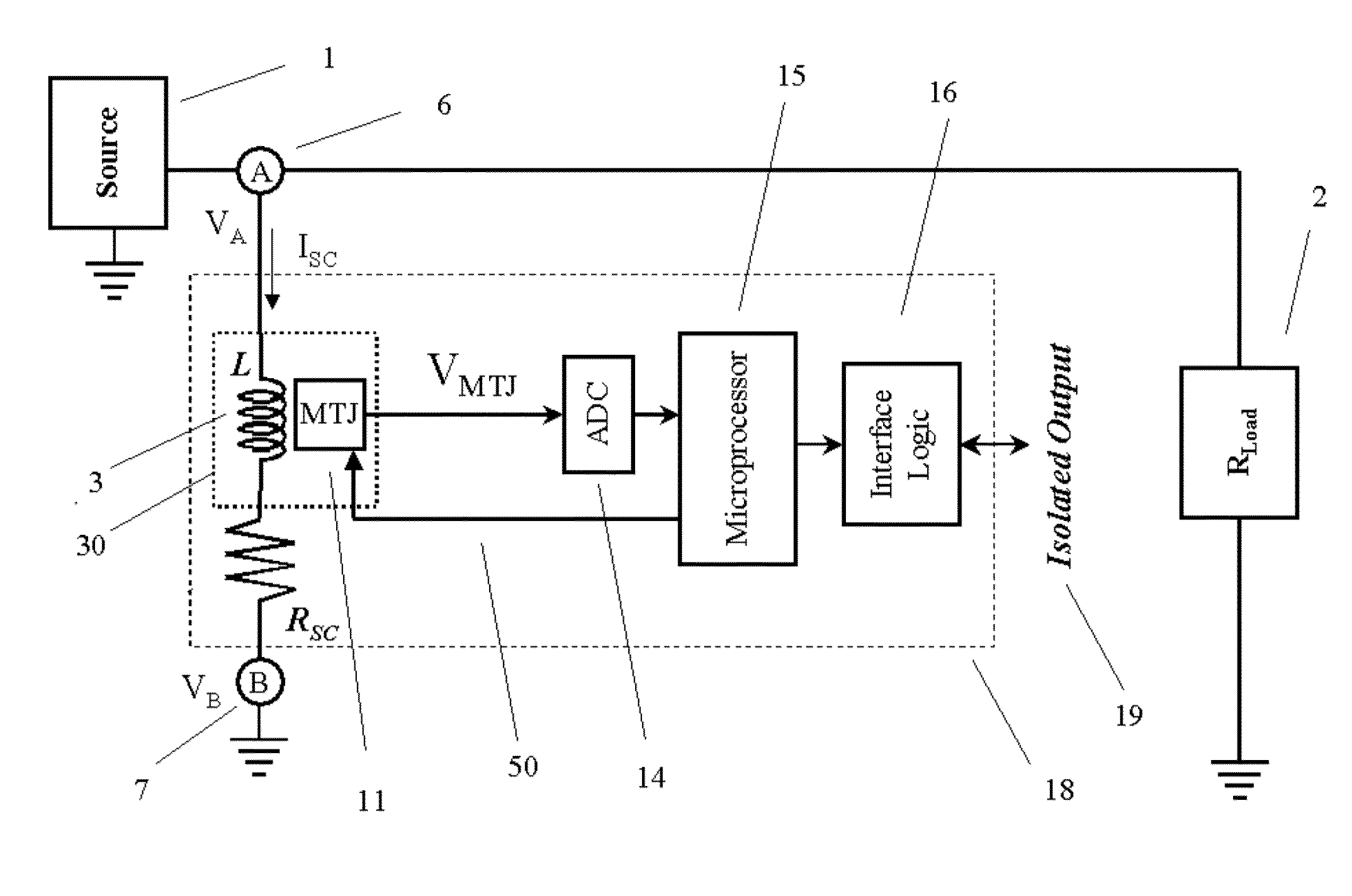
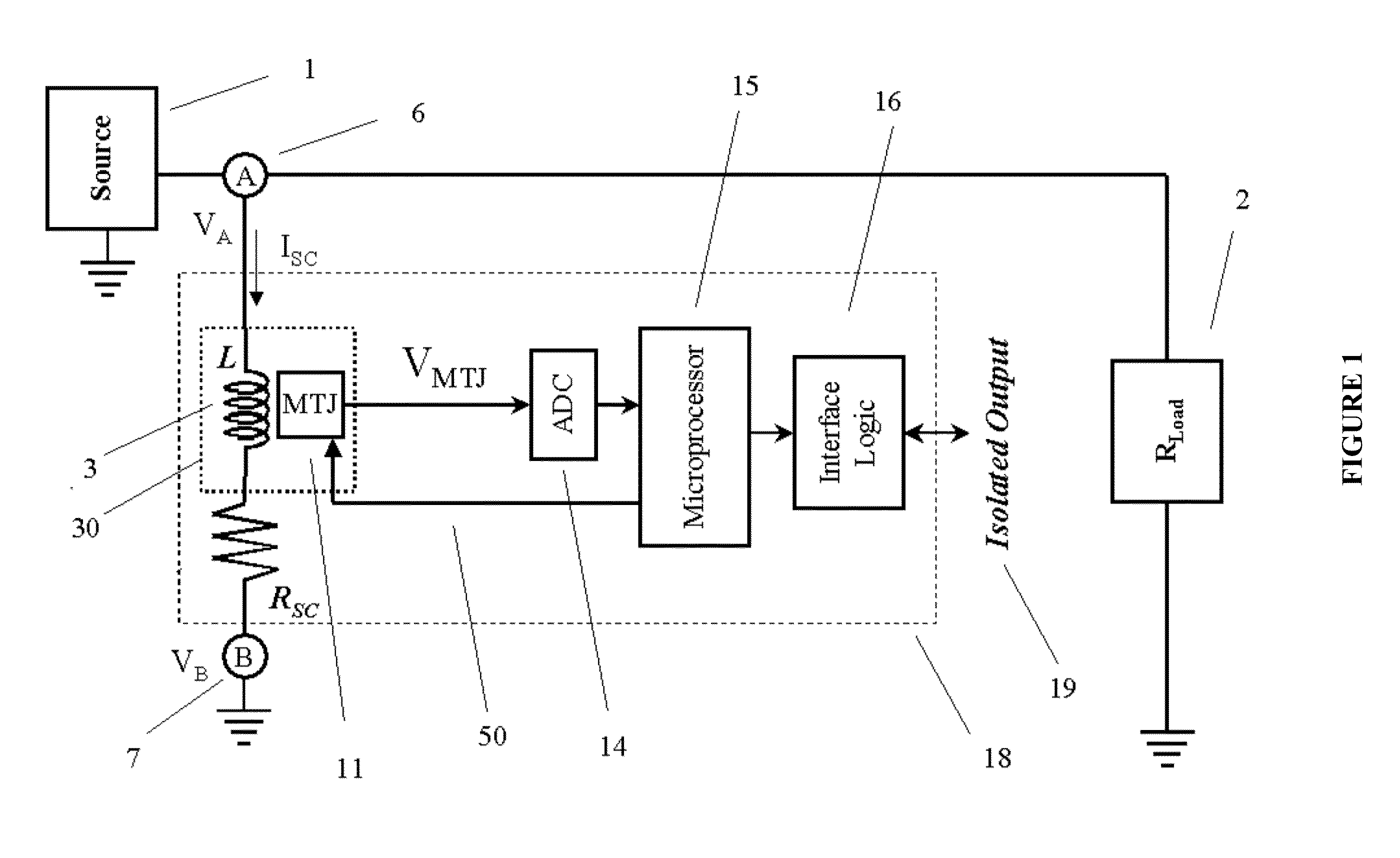
[0042]The single-package, galvanically isolated, voltage transducer of the present invention is shown generally as 18 in the Figures. Referring to FIG. 1, the input connections 6, 7 of voltage transducer 18 are connected to test points A and B associated with a power source 1, and load 2, in order to measure the differential voltage between points A and B. A shunt coil 3 within the voltage transducer 18 is connected in series to a resistor Rsc within the isolated voltage transducer 18. One end of the shunt coil 3 is connected to input 6 and one end of the resistor Rsc is connected to input 7. The voltage difference between A and B causes a current to flow through the shunt coil 3. The current flowing through the shunt coil, ISC generally has a magnitude of

ISC=(VA−VB) / Rsc=ΔV / Rsc  [EQ1]

[0043]Current ISC produces a magnetic field H, as it flows through the shunt coil 3.

[0044]The MTJ device 11 is magnetically coupled to the shunt coil 3. It is the object of the MTJ sensor 11 to detect H...


PUM


Abstract

A transducer is disclosed for detecting the AC and DC voltage difference between two nodes in an electrical circuit and electronically transmitting the measured voltage difference to an electrical system that is electrically isolated from the common mode potential of the two nodes. The voltage drop between two points in a circuit under test is determined by detecting the current flowing through a resistive shunt coil connected in parallel to the test points. Current through the resistive shunt coil is linearly proportional to the voltage difference between the test points, and it is detected by using a magnetic sensor that is separated from the shunt coil by an insulating dielectric barrier. The transducer can be packaged in a standard integrated circuit package in order to provide a small and low cost voltage transducer for test, measurement, control, and signal-isolation applications.

Description

FIELD OF THE INVENTION[0001]The present invention relates to an isolated analog voltage transducer utilizing magnetic tunnel junction (MTJ) devices, more specifically relates to a voltage transducer for measuring the voltage difference between the test points by using magnetic tunnel junction (MTJ) devices to measure the current flowing through a resistive shunt coil connected to the test points.BACKGROUND OF THE INVENTION[0002]Voltage measurements are an important part of industrial, consumer electronics, and medical electronics applications. Often these applications involve environments with hazardous voltages, transient signals, common-mode voltages, and fluctuating ground potentials capable of damaging electronic systems and in an extreme case, causing physical harm to a person in contact with the electronic device. To overcome these issues, electronic test, measurement, and control systems are often designed to isolate the measurement test points from the data acquisition elect...

Claims


Application Information

Patent Timeline
IPC IPC(8): G01R33/09G01R31/50
CPCG01R33/09G01R33/098G01R15/148G01R15/205G01R33/0017G01R33/091G01R31/50
Inventor DEAK, JAMES G.JIN, INSIKLEI, XIAOFENGSHEN, WEIFENGXUE, SONGSHENG
Owner MULTIDIMENSION TECH CO LTD
Why Eureka
Try Eureka