Vacuum glass panel and manufacturing method of same

a technology of vacuum glass and manufacturing method, which is applied in the field of vacuum glass panel, can solve the problems of complicated manufacturing process, high cost of method, and product error generation, and achieve the effect of improving the bearing power of a spacer, increasing the compression strength of the spacer, and optimizing the shape characteristics of the spacer

Active Publication Date: 2013-10-17
KONGJU NAT UNIV IND UNIV COOPERATION FOUND
View PDF32 Cites 16 Cited by
  • Summary
  • Abstract
  • Description
  • Claims
  • Application Information

AI Technical Summary

Benefits of technology

[0014]The present invention has been made in an effort to provide a vacuum glass panel which improves bearing power of a spacer by increasing a compression strength of the spacer and optimizing shape characteristics of the spacer and an arrangement type and an arrangement gap by considering a distribution of stresses applied to a glass plate.
[0015]The present invention has also been made in an effort to provide a method of manufacturing a vacuum glass panel which easily dispose the spacer on a large area glass plate and firmly fix the spacer to a designated position without omission or arrangement error.
[0016]The present invention has also been made in an effort to provide a vacuum glass panel and a manufacturing method of the same which solve deformation and discoloration problems of the glass plate according to the use of a sealing material and prevent a vacuum degree from deteriorating by degassing of the sealing material.
[0017]The present invention has also been made in an effort to provide a vacuum glass panel and a manufacturing method of the same, which simplify a manufacturing process, reduce manufacturing costs, and are advantageous to a large size.
[0046]According to an exemplary embodiment of the present invention, it is possible to improve bearing power of a spacer by increasing a compression strength of the spacer and optimize shape characteristics of the spacer and an arrangement type and an arrangement gap by considering a distribution of stresses applied to a glass plate. It is possible to easily dispose the spacer on a large area glass plate and firmly fix the spacer to a designated position without omission or arrangement fault. It is possible to solve deformation and discoloration problems of the glass plate according to the use of a sealing material and prevent a vacuum degree from deteriorating by degassing of the sealing material. It is possible to simplify a manufacturing process of the vacuum glass panel and reduce manufacturing costs.

Problems solved by technology

However, omission or errors in arrangements of the spacers frequently occur in the method, which may generate errors in products.
However, the method requires expensive equipment and has a complicated manufacturing process.
Further, a tensile stress is generated near the spacer in the external surfaces of the glass plate, and when the tensile stress exceeds a maximum allowable tensile stress, self-destruction occurs.
However, such a high temperature sealing method may create deformation or discoloration of the glass plate.
For example, in a case of a low emissivity glass plate, a metal coating film is oxidized and discolored, and as a result, a radiant heat blocking function may be lost.
However, in this case, a manufacturing cost of the vacuum glass panel is increased since the sealing material is expensive, and a degassing phenomenon is generated from the sealing material after being evacuated and thus a vacuum degree of the vacuum glass panel is reduced, thereby deteriorating the insulation performance.

Method used


Image

  • Vacuum glass panel and manufacturing method of same
  • Vacuum glass panel and manufacturing method of same
  • Vacuum glass panel and manufacturing method of same

Examples


Embodiment Construction

[0065]Hereinafter, the present invention will be described more fully hereinafter with reference to the accompanying drawings, in which exemplary embodiments of the invention are shown. As those skilled in the art would realize, the described embodiments may be modified in various different ways, all without departing from the spirit or scope of the present invention.

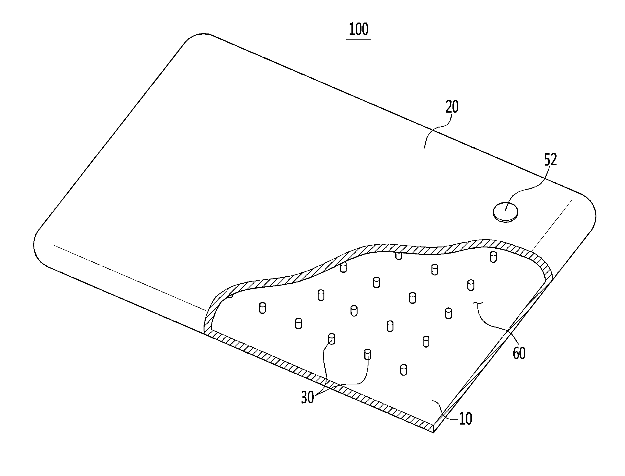
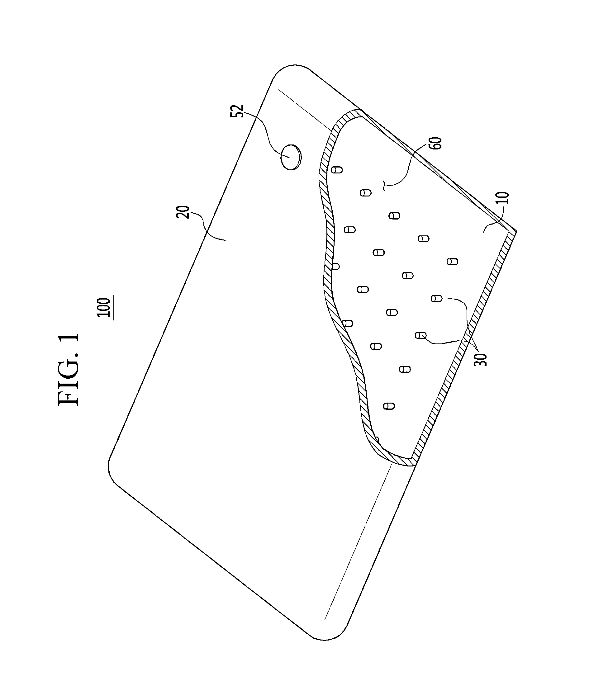
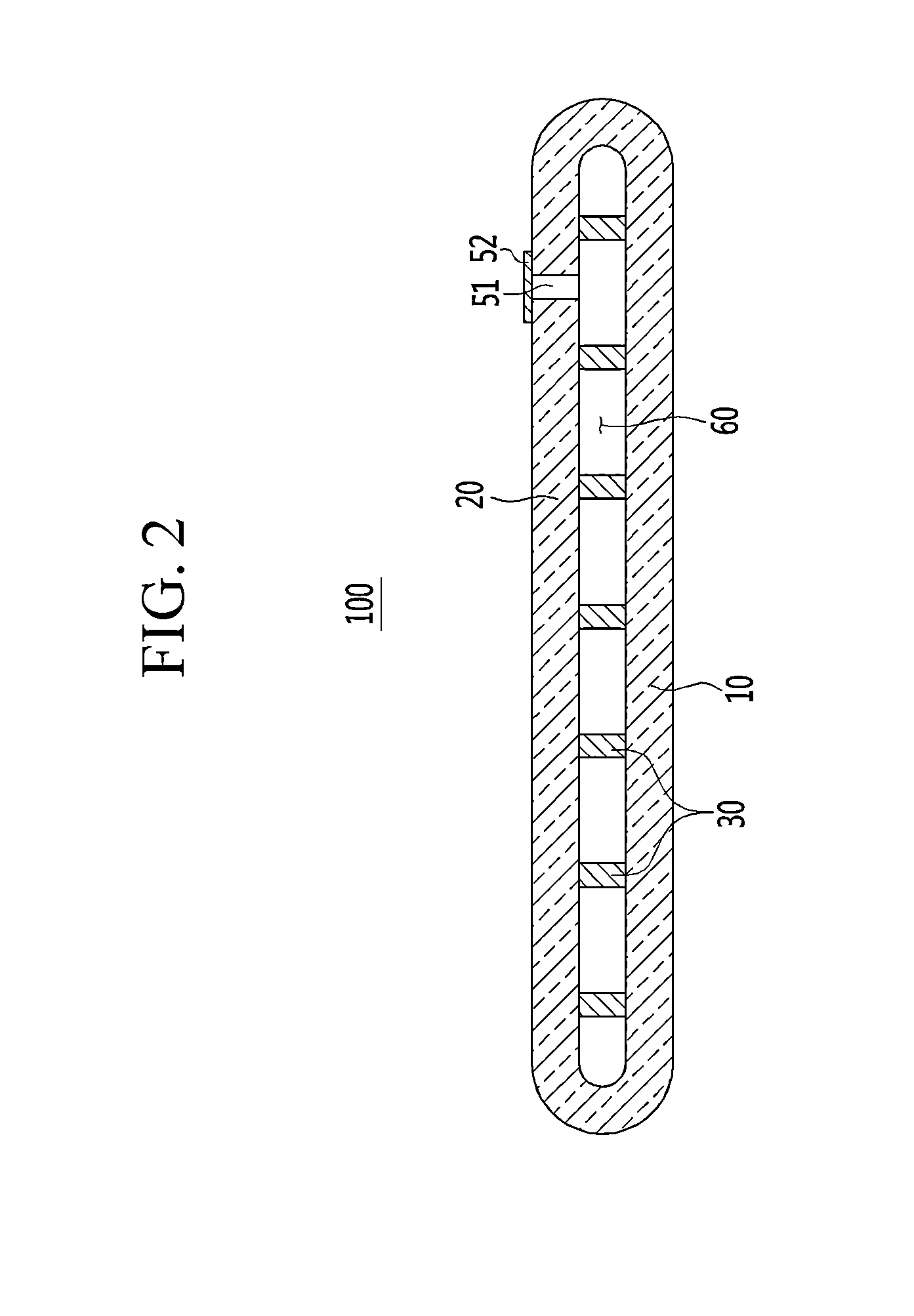
[0066]FIG. 1 is a partially cut-away perspective view of a vacuum glass panel according to an exemplary embodiment of the present invention, and FIG. 2 is a cross-sectional view of the vacuum glass panel illustrated in FIG. 1.

[0067]Referring to FIGS. 1 and 2, a vacuum glass panel 10 includes a first glass plate 11, a second glass plate 12 facing the first glass plate 11, a plurality of spacers 13 disposed between the first glass plate 11 and the second glass plate 12. Edges of the first glass plate 11 and the second glass plate 12 are in contact to seal a space between the two glass plates 11 and 12.

[0068]The first glas...


PUM

PropertyMeasurementUnit
sizeaaaaaaaaaa
diameteraaaaaaaaaa
heightaaaaaaaaaa

Abstract

Disclosed are a vacuum glass panel and a manufacturing method of the same. The vacuum glass panel according to the present invention includes a first glass plate, a second glass plate facing the first glass plate with a vacuum space therebetween, an edge of the second glass plate being in contact with the first glass plate, and a plurality of spacers disposed between the first glass plate and the second glass plates to separate the first glass plate and the second glass plate from each other. The plurality of spacers are formed of a glass including alumina (Al2O3) particles and silica (SiO2) particles.

Description

CROSS-REFERENCE TO RELATED APPLICATION[0001]This application claims priority to and the benefit of Korean Patent Application Nos. 10-2010-0127013, and 10-2010-0140262 filed in the Korean Intellectual Property Office on Dec. 13, 2010, and Dec. 31, 2010, the entire contents of which are incorporated herein by reference.BACKGROUND OF THE INVENTION[0002](a) Field of the Invention[0003]The present invention relates to a vacuum glass panel, and more particularly to, a plurality of spacers interposed between two glass plates to support an external force and an edge sealing technology integrally welding edges of two plates separated from each other.[0004](b) Description of the Related Art[0005]A vacuum glass panel has a structure where a vacuum space is formed between two glass plates, and receives attention as future door and window materials due to its insulation performance. The vacuum glass panel receives complex dynamic stresses such as pressure applied by atmospheric pressure, a tempe...

Claims


Application Information

Patent Timeline
Patent Type & Authority Applications(United States)
IPC IPC(8): E06B3/66E06B3/673
CPCE06B3/6612E06B3/6736C03B23/245E06B3/6608E06B3/66304Y10T428/231Y02A30/249Y02B80/22
Inventor JEON, EUY-SIKMOON, SANG-INKIM, JEONG-BAE
Owner KONGJU NAT UNIV IND UNIV COOPERATION FOUND
Why Eureka
Try Eureka