Power storage device and method for manufacturing the same

a technology of power storage and power storage device, which is applied in the manufacture of final products, cell components, nanobatteries, etc., can solve the problems of not easy to form a solid secondary battery as a sheet, the film is easily flaked and cracked, and the positive electrode and the negative electrode are likely to be short-circuited, etc., to achieve high reliability, high resistance to entry of contaminant, and high reliability of power storage devi

Active Publication Date: 2013-10-17
SEMICON ENERGY LAB CO LTD
View PDF10 Cites 72 Cited by
  • Summary
  • Abstract
  • Description
  • Claims
  • Application Information

AI Technical Summary

Benefits of technology

[0016]In the power storage device having a structure described above, although each of the power storage elements does not have flexibility, the substrate where the power storage elements are provided is formed using a material having flexibility, and thus the power storage device has flexibility as a whole and can be curved and bent. Further, each of the power storage elements is sealed with the exterior body

Problems solved by technology

However, such a solid secondary battery has a problem in that an electrolyte layer also needs to be thin, so that a positive electrode and a negative electrode are likely to be short-circuited when the solid secondary battery is curved or bent.
In particular, a solid secondary battery is wholly formed using solids a

Method used


Image

  • Power storage device and method for manufacturing the same
  • Power storage device and method for manufacturing the same
  • Power storage device and method for manufacturing the same

Examples


embodiment 1

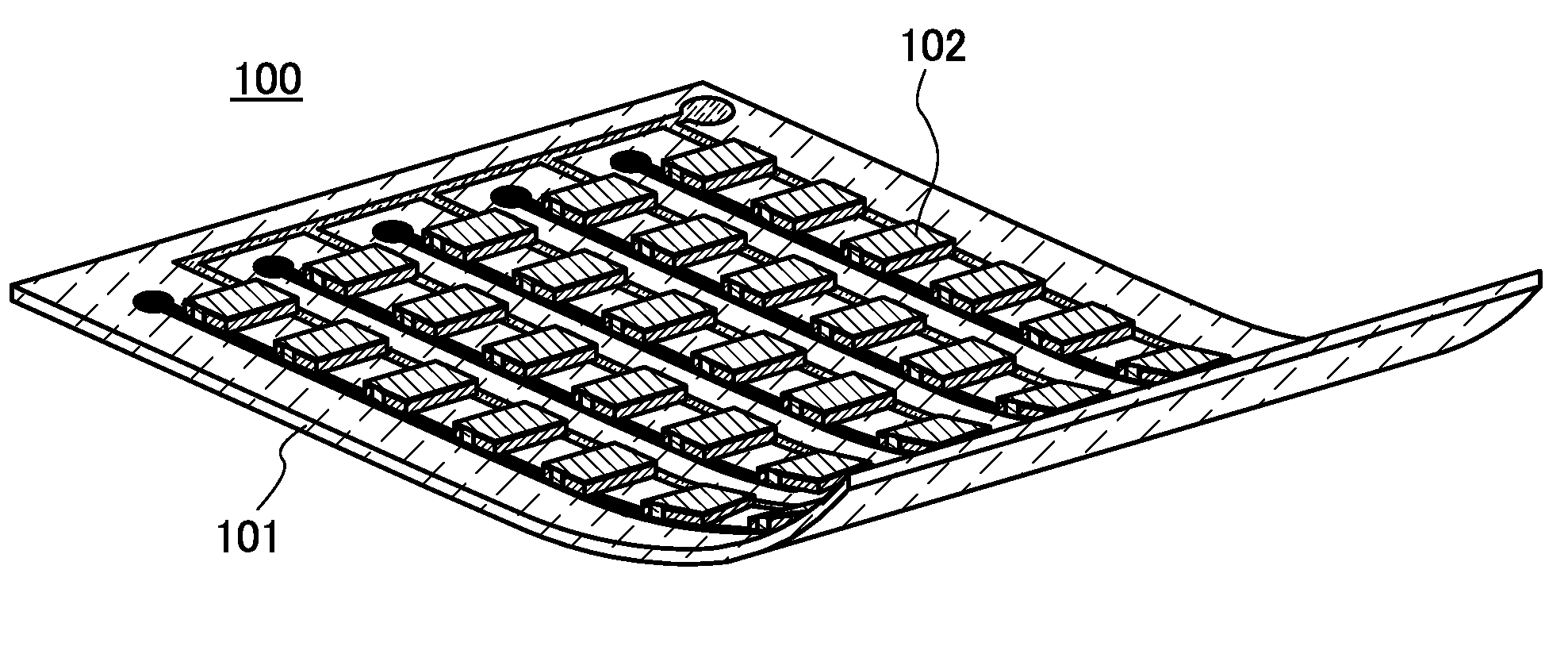
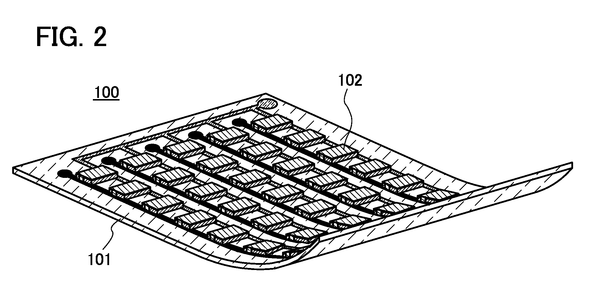
[0034]In this embodiment, a flexible and highly reliable power storage device is described with reference to FIGS. 1A to 1D, FIG. 2, and FIG. 3. In this embodiment, a lithium secondary battery is used as an example of a power storage device.

[0035]Note that a lithium secondary battery refers to a secondary battery where lithium ions are used as carrier ions. Examples of carrier ions which can be used instead of lithium ions include alkali-metal ions such as sodium ions and potassium ions; alkaline-earth metal ions such as calcium ions, strontium ions, and barium ions; beryllium ions; magnesium ions; and the like.

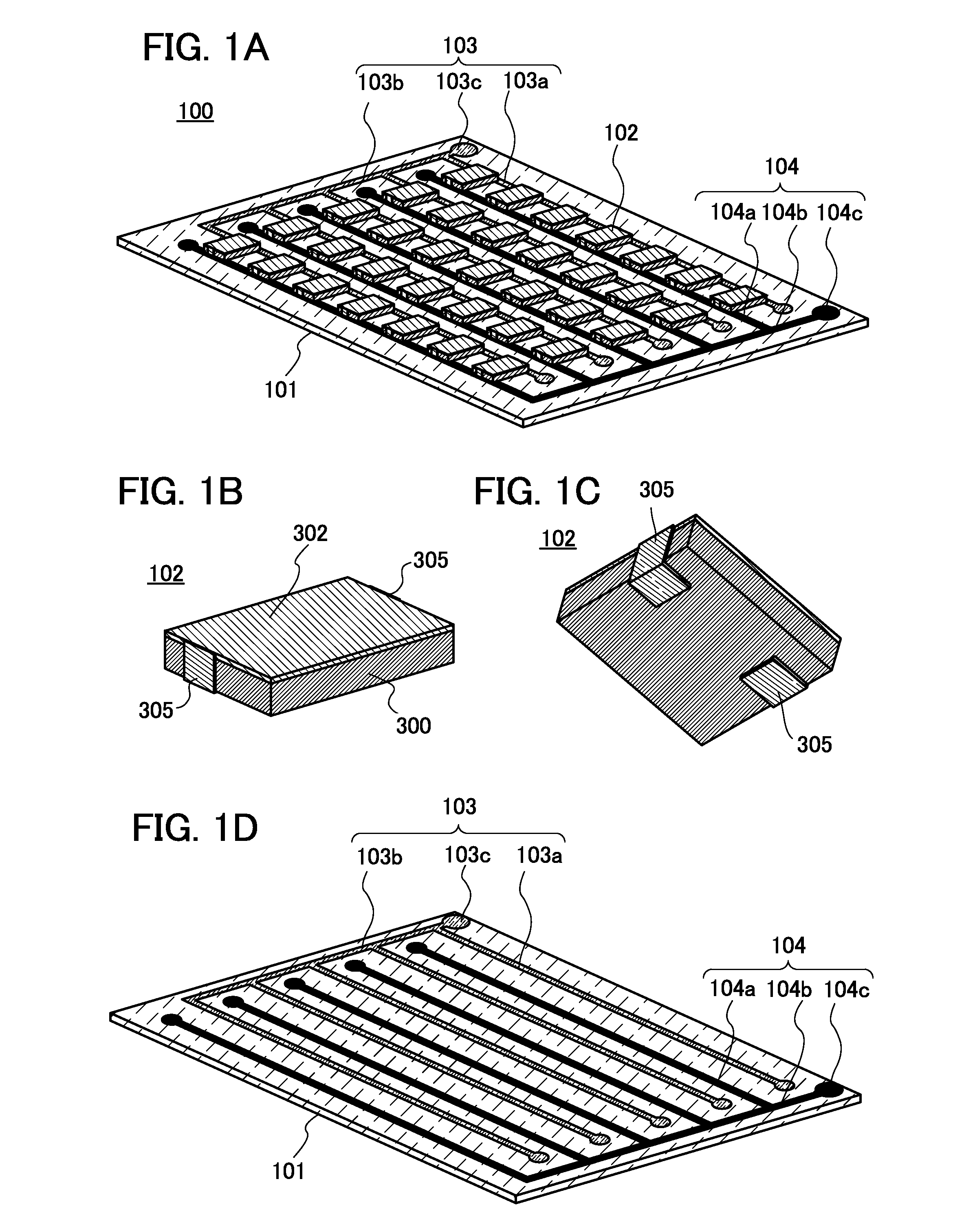
[0036]FIG. 1A is a bird's-eye schematic view illustrating a power storage device 100 which is described in this embodiment. The power storage device 100 includes a flexible substrate 101, power storage elements 102, a positive electrode lead 103, and a negative electrode lead 104.

[0037]As the flexible substrate 101, a substrate made of a resin material can be used. The use of...

embodiment 2

[0058]In this embodiment, an example of a method for manufacturing the power storage element included in the flexible power storage device which is described in Embodiment 1 is described with reference to FIGS. 4A and 4B, FIGS. 5A and 5B, FIG. 6, FIGS. 7A to 7C, FIGS. 8A to 8E, and FIGS. 9A to 9C.

[0059](Structure of Stack Body and Manufacturing Method Thereof)

[0060]The power storage element 102 described above includes a stack body 200 for storing power in the exterior body 300. As illustrated in FIG. 4A, the stack body 200 includes a sheet-like positive electrode 201, a sheet-like electrolyte 202, and a sheet-like negative electrode 203. Further, the negative electrode 203 is surrounded by a bag-like separator 204. Furthermore, a part of the positive electrode 201 and part of the negative electrode 203 are extended outside for connection with the tabs 305 each of which is provided on the side surface and the bottom surface of the power storage element 102. The positive electrode 20...

embodiment 3

[0085]In this embodiment, structures of the positive electrode and the negative electrode used in the stack bodies which are described in Embodiments 1 and 2, and manufacturing methods thereof are described.

[0086](Positive Electrode and Manufacturing Method Thereof)

[0087]First, a positive electrode and a manufacturing method thereof are described. FIG. 10A is a cross-sectional view of a positive electrode 500. In the positive electrode 500, positive electrode mix layers 502 are formed on both surfaces of a positive electrode current collector 501.

[0088]For the positive electrode current collector 501, a highly conductive material such as a metal typified by stainless steel, gold, platinum, zinc, iron, copper, aluminum, or titanium, or an alloy thereof can be used. Note that the positive electrode current collector 501 can be formed using an aluminum alloy to which an element which improves heat resistance, such as silicon, titanium, neodymium, scandium, or molybdenum, is added. Furt...


PUM

PropertyMeasurementUnit
Thermoplasticityaaaaaaaaaa

Abstract

To provide a flexible, highly reliable, and sheet-like power storage device. The power storage device including a flexible substrate; a positive electrode lead and a negative electrode lead over the flexible substrate; and a plurality of power storage elements over the flexible substrate. The plurality of power storage elements each includes a stack body including a sheet-like positive electrode; a sheet-like negative electrode; and an electrolyte therebetween in an exterior body. An edge portion of the sheet-like positive electrode which extends to the outside of the exterior body is electrically connected to the positive electrode lead through a positive electrode tab provided for the exterior body. An edge portion of the sheet-like negative electrode which extends to the outside of the exterior body is electrically connected to the negative electrode lead through a negative electrode tab provided for the exterior body.

Description

BACKGROUND OF THE INVENTION[0001]1. Field of the Invention[0002]The present invention relates to a power storage device and a method for manufacturing the power storage device.[0003]2. Description of the Related Art[0004]In recent years, lithium secondary batteries as power storage devices have been widely used as power supplies of consumer electronic devices such as game machines and information terminals typified by mobile phones and smartphones.[0005]For such electronic devices, the need of power storage devices having not only long life and high capacity but also sheet-like shapes and flexibility for reductions in weight and size and a greater freedom for design of outer shapes has been increased. Flexible sheet-like power storage devices can be provided even for curved or bent portions and thin portions such as band portions of wristwatches, clothes, and thin electric alliances.[0006]Lithium secondary batteries which are conventional nonaqueous secondary batteries each generall...

Claims


Application Information

Patent Timeline
IPC IPC(8): H01M10/04
CPCH01M10/0436H01M2010/0495H01M2300/0082Y02E60/10Y10T29/49108Y02P70/50
Inventor TAKAHASHI, MINORUTAJIMA, RYOTA
Owner SEMICON ENERGY LAB CO LTD
Why Eureka
Try Eureka