Methods and apparatuses for detection of positional freedom of particles in biological and chemical analyses and applications in immunodiagnostics

a technology of positional freedom and particle, applied in the field of methods and apparatuses, can solve the problems of reducing data quality, long incubation time, added expense, etc., and achieve the effects of reducing the amount of positional freedom, increasing the amount of particle motion, and enhancing the degree of movemen

Inactive Publication Date: 2013-10-17
ARRYX INC
View PDF1 Cites 29 Cited by
  • Summary
  • Abstract
  • Description
  • Claims
  • Application Information

AI Technical Summary

Benefits of technology

[0016]In one embodiment, an in-line microscope apparatus designed to measure the mobility of particles (i.e., cells) in order to infer surface interactions (i.e., presence or absence of specific surface-particle interactions), and / or collective diffusion / visco-elastic properties of the particle dispersion (e.g., effective viscosity), is used. In another embodiment, a camera and a computer are included in the microscopy apparatus, in order to image different areas of the sample, and to assist in quantifying and analyzing the results obtained, to determine the binding reactions of the particles with capture surface regions on the substrate on which the particles are disposed. Thus, the assay methods of the present invention may be implemented as a computer program product for use with the computer system.
[0058]Further embodiments of the present invention are based on the discovery that for at least some probe-types, nonspecific binding of settled particles occurs at a different rate than specific binding. As a result, it has been discovered that one can measure a positional fluctuation signal based on early time points after settling of the particles. Tracking of the evolution of the positional fluctuation measurements over time may allow for improved discrimination of non-specific binding from specific binding. Alternately, the system may be thought of as having multiple effects which occur with different time evolutions (for example, with different characteristic timescales or progression rates) and by tracking the evolution over time, the level of each contribution may be determined. For example, in a simple case where nonspecific binding is found to occur rapidly compared to specific binding, the early positional fluctuation may be subtracted from a positional fluctuation measurement based on later time points. In other words, the computation of positional fluctuation may include a step in which the computer program operates to calculate a measure related to the time evolution of the particle position and optionally corrects for nonspecific binding that occurs with a greater kinetic time-constant than the time-constant for nonspecific binding. As noted above, this may be done through curve-fitting or other algorithms known in the arts of kinetic or molecular assay technology.

Problems solved by technology

However, a major limitation of conventional arrays is that long incubation times are usually required to reach a degree of binding that is sufficiently close to equilibrium to achieve the desired sensitivity.
Such delays can cause added expense, preclude use in emergency situations, and reduce data quality due to degradation of reagents and increases in non-specific (background) signal during the protracted incubation times. Other limitations of conventional approaches include the need for analyte labeling steps and stringent washing steps, which introduce additional costs in terms of labor and equipment, and may impact data quality.
Further, microplate based approaches use relatively large volumes of test samples and reagents.
Ensuring that blood typing is performed accurately is extremely important because RBCs from different individuals may have different antigens on their surfaces, and transfusion of whole blood or certain blood components from a donor having certain RBC antigens to a patient that lacks those antigens may cause an adverse transfusion reaction in the patient.
Thus, the potential for spurious results can occur due to possible immunization against blood cell antigens that is undetectable due to limits on measurement sensitivity or diminishing antibody concentration (titer) within an immunized patient's blood over time, or may also occur due to a possible variation in antibody titer and reactivity from person to person, or a potential variability in reagent specificity.
Present techniques for determining blood type are limited in their sensitivity, speed, and ability to test a sample for a large number of analytes.
For example, the fact that conventional blood typing methods require agglutination or bulk surface binding, where most RBCs have to bind (and in many cases must bind strongly by forming multivalent attachments), limits the speed and sensitivity of the testing.
Further, current technologies require a relatively large amount of blood (e.g., about 3 mL) for testing.

Method used


Image

  • Methods and apparatuses for detection of positional freedom of particles in biological and chemical analyses and applications in immunodiagnostics
  • Methods and apparatuses for detection of positional freedom of particles in biological and chemical analyses and applications in immunodiagnostics
  • Methods and apparatuses for detection of positional freedom of particles in biological and chemical analyses and applications in immunodiagnostics

Examples


embodiment 1

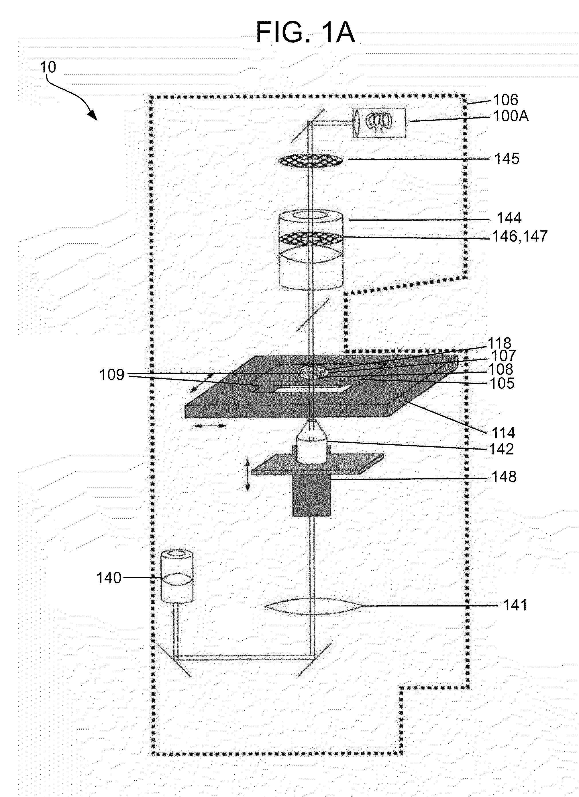
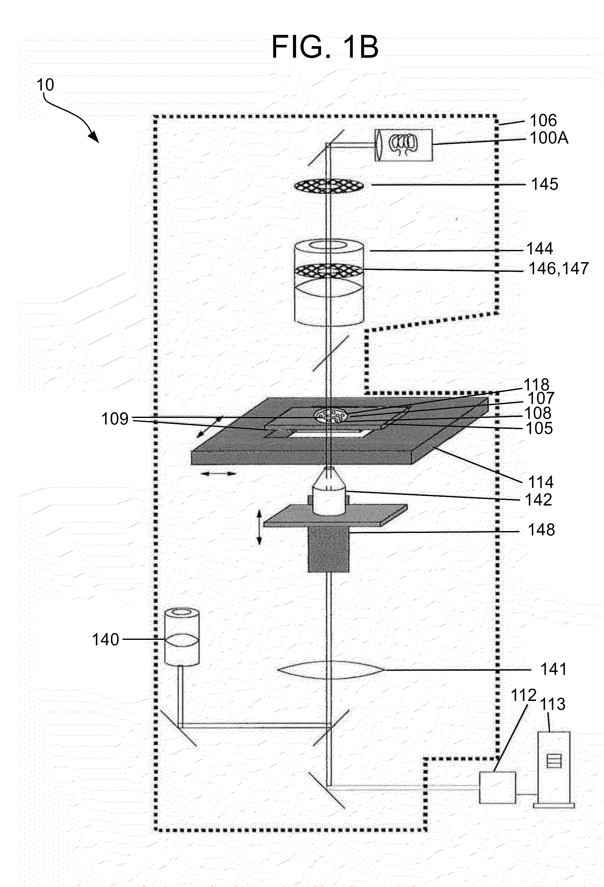
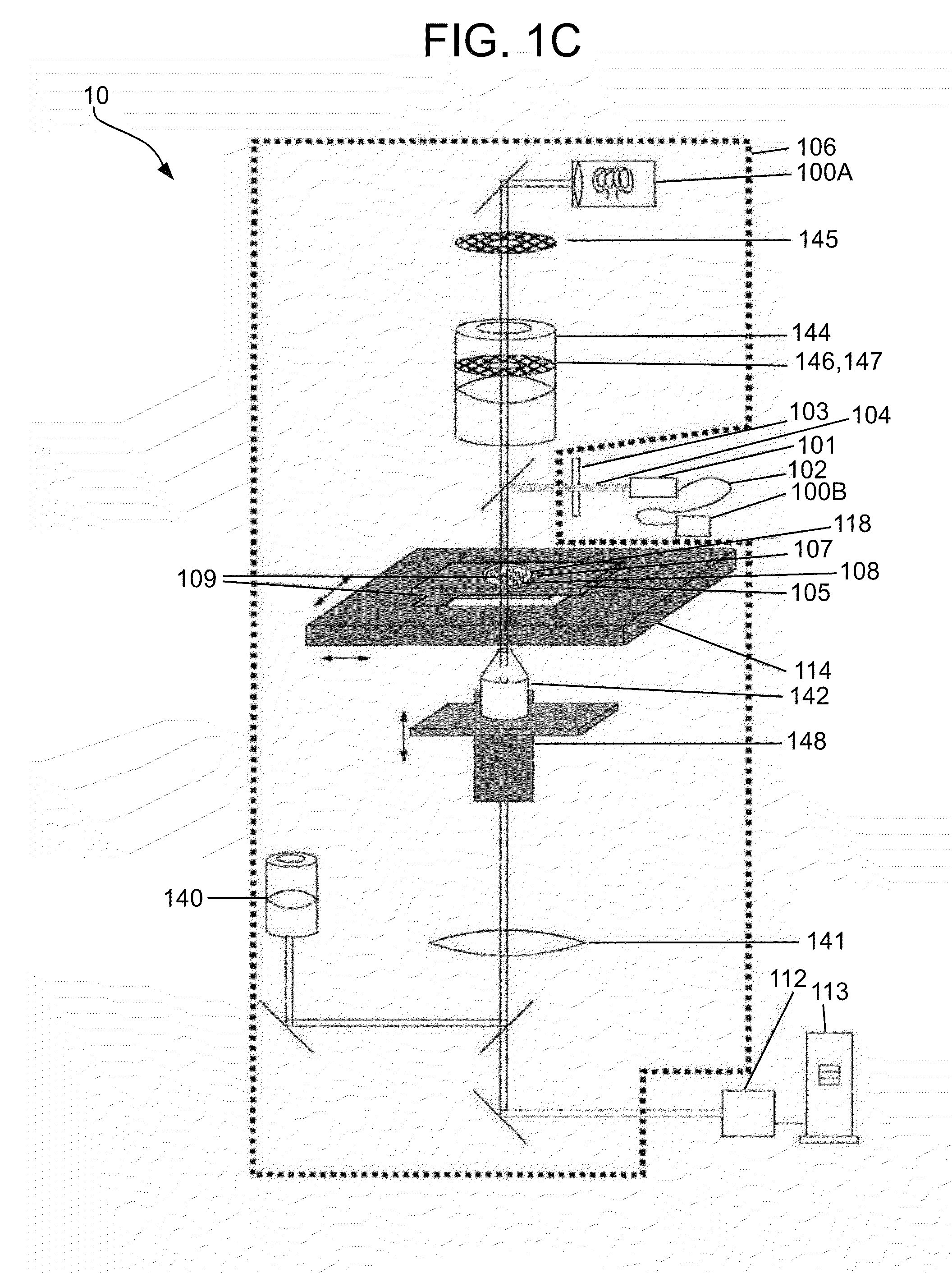
[0150]In one embodiment consistent with the present invention, the sample holder 105 includes a simple microscope slide made of glass or plastic, with the particles 108 being disposed or settled on its transparent surface 109 (see FIGS. 1A-1C). Typically a cover slip will be placed over the sample.

embodiment 2

[0151]In yet another embodiment consistent with the present invention, the transparent sample holder 105 includes a simple passive microfluidic cartridge 116 (see FIG. 1F). In this embodiment, the closed sample microfluidic cartridge 116 includes two ports (i.e., inlet 401, outlet 402) and a chamber 118 therebetween (see drawing A). A sensing array 200 is bonded underneath with capture surface regions 210, 211, 212, and is treated with the appropriate chemistry for the particular application desired. The sample solution 107 of particles 108 is introduced into the inlet 401 and the particles settle onto the surface 109, and capture surface regions 210, 211, 212 of sensing array 200 (see drawings B-D). Binding interactions may be observed using the microscopy apparatus 10.

embodiment 3

[0152]In yet another embodiment consistent with the present invention, the transparent sample holder 105 includes a well plate (standard microtiter plate or custom well plate or other cartridge with wells). In this embodiment, the open well sample cartridge 161 includes a transparent sample holder 105 with an opening in the center for a chamber 118 (see FIG. 1G, drawing A). A cover glass 162 is bonded underneath. The cover glass 162 will be treated with the appropriate chemistry for the particular application desired. A cap (like cap 417 in FIG. 1H, for example) may be disposed over the opening to the chamber 118. A sample solution 107 of particles 108 is disposed in the chamber 118 and settles on the surface 109, including capture surface regions 210, 211, 212 (see FIG. 1G, drawings B-C), and binding interactions may be observed using the microscopy apparatus 10.


PUM

PropertyMeasurementUnit
coherence lengthaaaaaaaaaa
distanceaaaaaaaaaa

Abstract

The present invention relates to methods and apparatuses for the detection of positional freedom of particles used in biological, biochemical, physical, biophysical, and chemical analyses. In particular, the present invention relates to methods and apparatuses which can detect and characterize a population of particles / cells based upon their detected mobility. In one embodiment consistent with the invention, detection of certain cells is based on differences detected in populations of cells that bind to a substrate and those that exhibit weaker binding forces. Initially, cells are settled on the substrate, and in the presence of gravitational, natural thermodynamic pressure fluctuations, and other random or applied forces, some of the particles may exhibit translational movement. Particle movement is detected, and measurements are computed, according to the methods and apparatuses of the present invention, to determine the binding of specific analytes.

Description

CROSS-REFERENCE TO RELATED APPLICATIONS[0001]The present invention claims priority from U.S. Provisional Patent Application No. 61 / 348,072, filed May 25, 2010, and U.S. Provisional Patent Application No. 61 / 347,946, filed May 25, 2010, the contents of both of which are herein incorporated by reference in their entirety.BACKGROUND OF THE INVENTION[0002]1. Field of the Invention[0003]The present invention relates to methods and apparatuses for the detection of positional freedom of particles used in biological, biochemical, biophysical, physical, and chemical analyses. Major applications of the present invention include immunodiagnostics, such as blood typing and infectious disease screening.[0004]2. Description of the Related Art[0005]The use of arrayed molecules in formats such as microplates and biochips allows for an ever increasing amount of information to be retrieved about the natural world. Although many variants are known, use of such arrays typically involves immobilizing pr...

Claims


Application Information

Patent Timeline
Patent Type & Authority Applications(United States)
IPC IPC(8): G01N33/80G16B25/00
CPCG01N33/80G01N15/0211G01N15/1463G01N21/453G01N33/5029G01N33/54313G01N2015/0216G01N2015/1497G03H1/0866G03H2001/005G03H2001/221G03H1/0443C40B30/04G01N33/53G16B99/00G16B25/00
Inventor KNUTSON, CHRISTOPHERAKCAKIR, OSMANFU, HAOJUN
Owner ARRYX INC
Why Eureka
Try Eureka