
Acoustic transducers with perforated membranes

a technology of perforated membranes and transducers, which is applied in the direction of electrostatic transducer microphones, semiconductor devices, electrostatic/electrostrictive/magnetostrictive devices, etc., can solve the problems of reducing the robustness of the backplate, reducing the sensor performance, and reducing the relative movement of the plate, so as to avoid the build-up of stress and increase the robustness

Active Publication Date: 2013-10-31
NXP BV
View PDF1 Cites 20 Cited by
  • Summary
  • Abstract
  • Description
  • Claims
  • Application Information

AI Technical Summary

Benefits of technology

The patent describes a design for a membrane structure that is symmetrically stiff and has uniform stress distribution. This design reduces the risk of cracking and improves mechanical strength. The membrane is clamped along its full perimeter, increasing its robustness and reducing body noise. The structure is also designed to have a spring function, which suppresses body noise and avoids stress concentration at discrete anchors. Overall, the design provides a high degree of symmetry and is less susceptible to manufacturing defects or unwanted resonances.

Problems solved by technology

Due to differences in plate properties, the plates are actuated differently, so that the body noise results in relative movement of the plates.
In the case of a microphone sensor, this relative movement is undesirably detected and, thus, reduces the sensor performance.
This stress built-up decreases the robustness of these backplates, and means the design is sensitive to stress gradients.
This might lead to processing problems associated with the resulting inhomogeneity of the sacrificial layer etch.
An issue in the fabrication of MEMS devices is that the stress and the stress gradient are difficult to control in processing.
If frequency matching is desired, this phenomena can be a sizable obstacle.
At very high perforation degrees, manufacturing becomes difficult, the perforated membrane becomes fragile, and the capacitance and signal strength decrease.
Another problem is that of the mechanical toughness of perforated membranes.
Rounded edges are beneficial, but a circular shape is not the optimum in terms of electro-mechanical signal and noise generation.

Method used


Image

  • Acoustic transducers with perforated membranes
  • Acoustic transducers with perforated membranes
  • Acoustic transducers with perforated membranes

Examples


Embodiment Construction

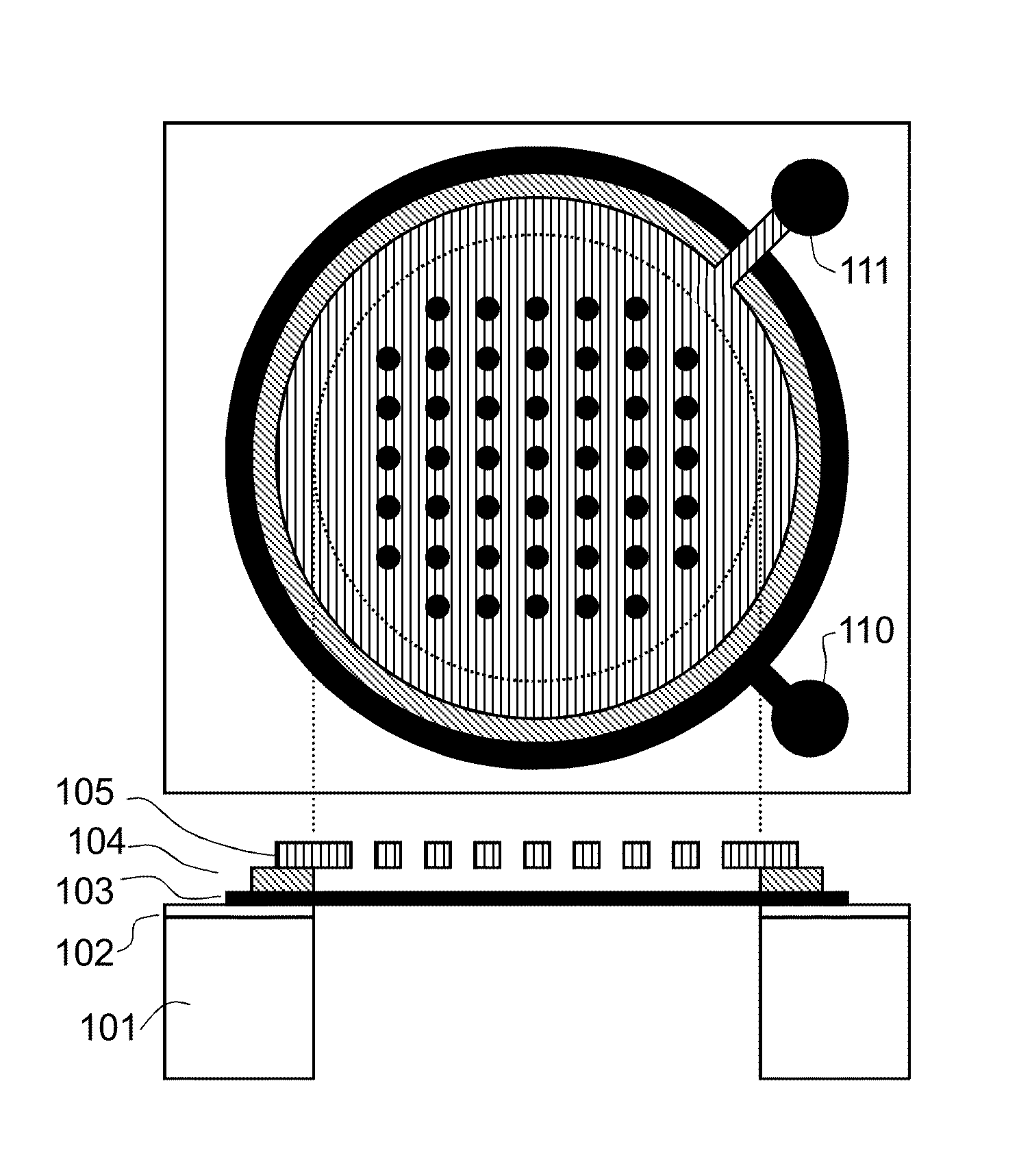
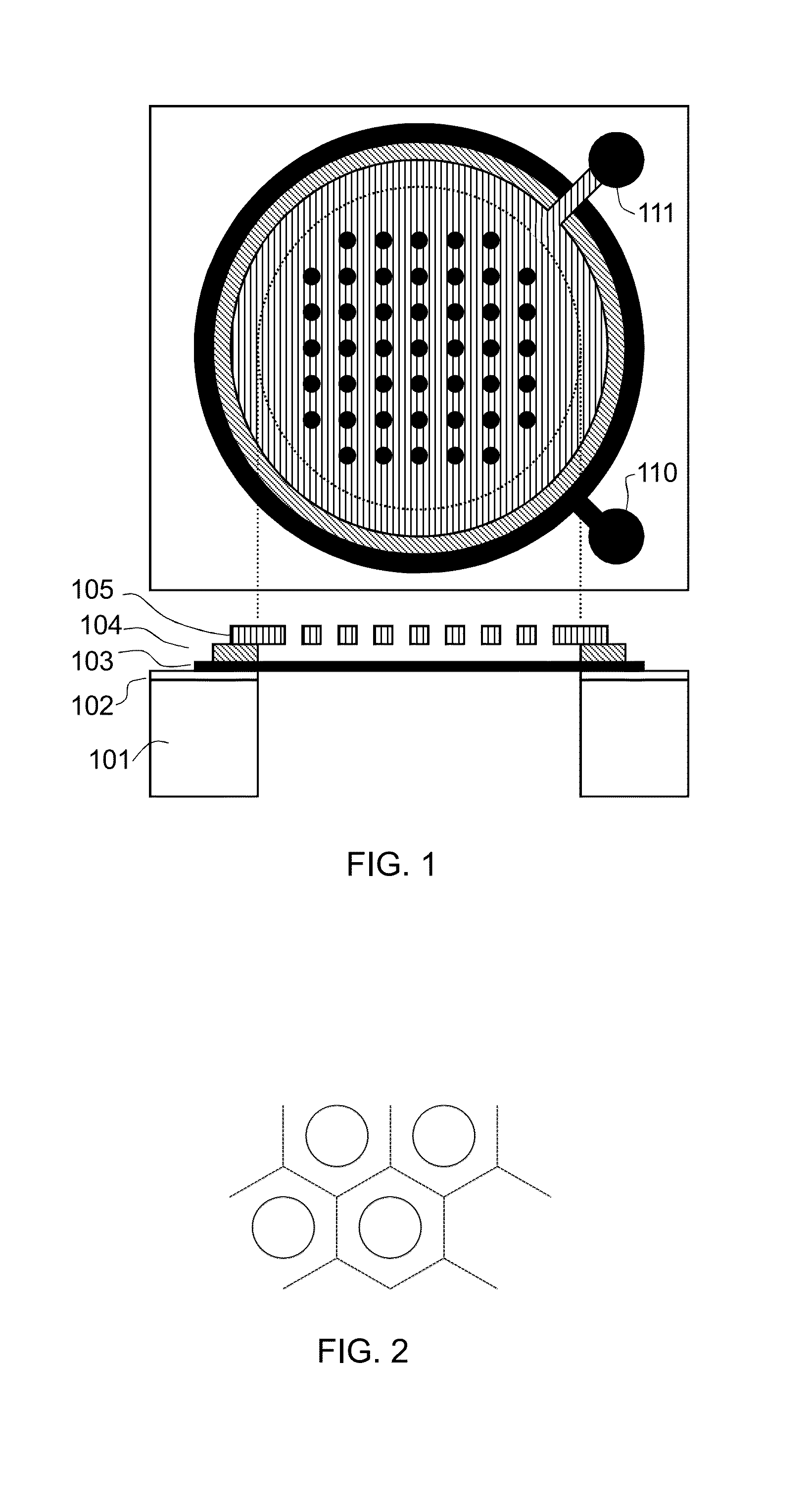
[0046]The invention provides a MEMS device such as a microphone, which uses a fixed perforated plate. The fixed plate has an area formed as a polygonal grid of unit cells, wherein each unit cell comprises a line of material following a path around the polygon thereby defining an opening in the centre of the polygon. The fixed plate area may be the full area of the fixed membrane.

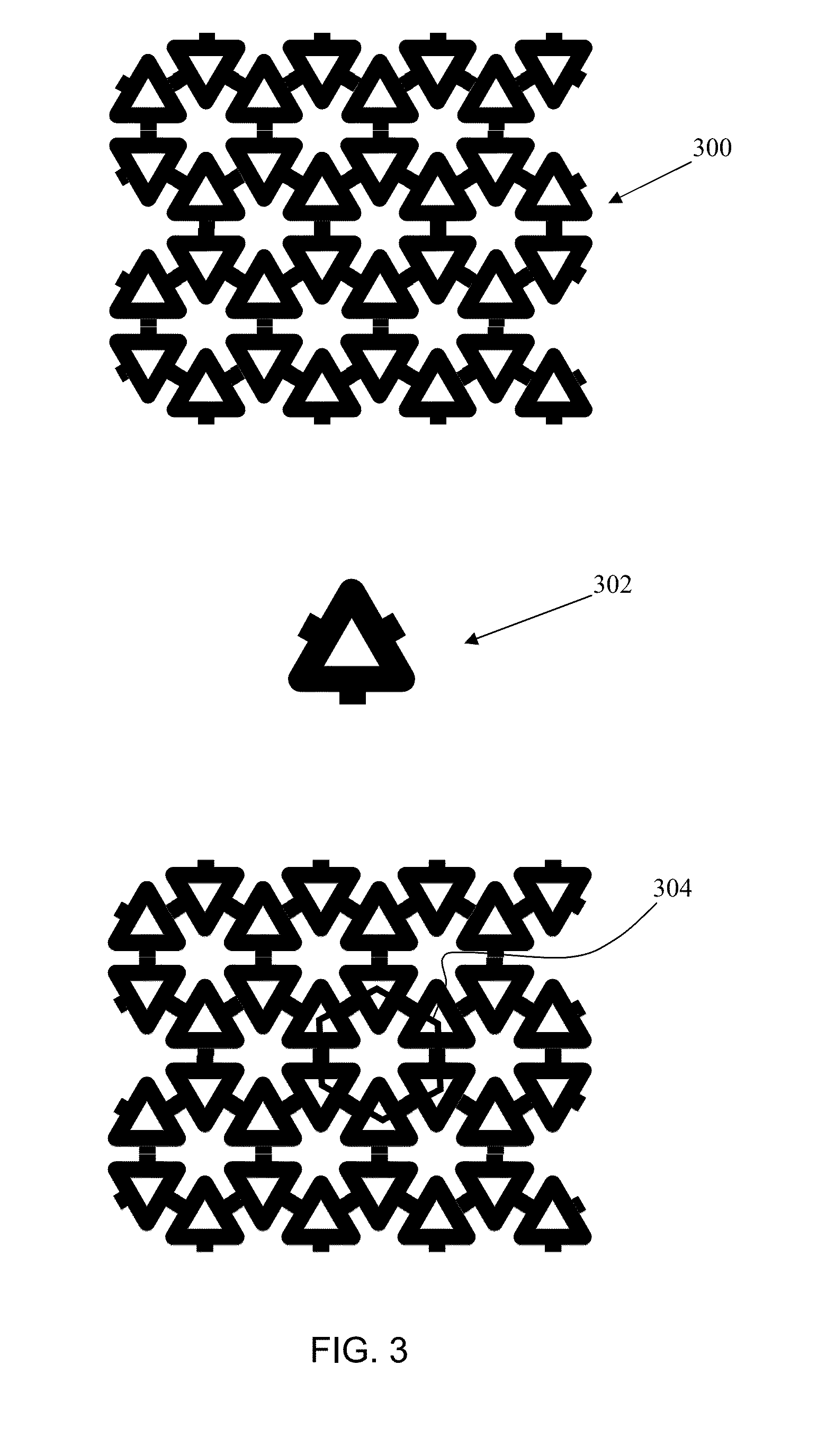
[0047]In one aspect, the line of material forms a path along each side of a polygon which forms a track which extends at least once inwardly from the polygon perimeter towards the centre of the polygon and back outwardly to the polygon perimeter. This defines a meandering hexagon side wall, which functions as a local spring suspension.

[0048]In another aspect, the line of material has a non-uniform width with a wider width in the centre of the polygon side that at the ends of the polygon side. This defines a large opening (because the line width is narrow at the corner), but the non-uniform width enables a me...


PUM


Abstract

A MEMS device, such as a microphone, uses a perforated plate. The plate comprises an array of holes across the plate area. The plate has an area formed as a grid of polygonal cells, wherein each cell comprises a line of material following a path around the polygon thereby defining an opening in the centre. In one aspect, the line of material forms a path along each side of the polygon which forms a track which extends at least once inwardly from the polygon perimeter towards the centre of the polygon and back outwardly to the polygon perimeter. This defines a meandering hexagon side wall, which functions as a local spring suspension.

Description

CROSS-REFERENCE TO RELATED APPLICATIONS[0001]This application claims the priority under 35 U.S.C. §119 of European patent application no. 12166028.6, filed on Apr. 27, 2012, the contents of which are incorporated by reference herein.[0002]This invention relates to acoustic transducers with perforated membranes. In particular, this invention relates to the design of perforated membranes to tolerate tensile stresses and to reduce body noise.BACKGROUND OF THE INVENTION[0003]Condenser microphones consist of two membranes: a membrane that is actuated by the sound pressure and a perforated membrane which forms a counter-electrode (“backplate”) that does not move in response to sound pressure, as the perforations render it acoustically transparent. The perforations allow the first membrane to move without pressure build-up in the volume between membrane and backplate.[0004]In the presence of mechanical vibrations, also known as “body noise”, both plates are actuated. Due to differences in ...

Claims


Application Information

Patent Timeline
IPC IPC(8): B81B3/00
CPCB81B3/0072H04R19/005H04R19/04H04R2410/03
Inventor REIMANN, KLAUSBOMINAAR-SILKENS, IRISVAN LIPPEN, TWANPIJNENBURG, REMCO HENRICUS WILHELMUS
Owner NXP BV
Learn More