Liquid crystal display device

a display device and liquid crystal technology, applied in static indicating devices, instruments, non-linear optics, etc., can solve the problems of motion blur characteristics of devices, image quality degradation, and difficulty in securing a time for turning on switching elements for each pixel, so as to reduce the number of stages and minimize the area occupied by the gate driving unit

Active Publication Date: 2013-10-31
LG DISPLAY CO LTD
View PDF1 Cites 23 Cited by
  • Summary
  • Abstract
  • Description
  • Claims
  • Application Information

AI Technical Summary

Benefits of technology

[0020]The present invention has been contrived to solve the foregoing problem, an object of the present invention is to minimize an area occupied by a gate driving unit on the liquid crystal panel in a GIP type dual gate structure liquid crystal display device, thereby implementing a narrow bezel liquid type crystal display device.
[0021]Furthermore, another object of the present invention is to solve image quality deterioration due to a discharge period delay caused by the signal delay of the gate line in a 120 Hz liquid crystal display device.
[0040]According to a preferred embodiment of the present invention, the number of stages may be reduced through the structure of alternately outputting a gate driving voltage other than the structure of simultaneously outputting a gate driving voltage from two gate driving units in a dual GIP type liquid crystal display, thereby having an effect capable of minimizing an area occupied by the gate driving unit.
[0041]Furthermore, according to the present invention, a separate discharge means may be provided for each stage of the gate driving unit to discharge a gate line in synchronization with the output of a subsequent stage for each one horizontal period (1H), thereby having another effect capable of solving the image deterioration of the liquid crystal display device due to a discharge period delay.

Problems solved by technology

Furthermore, the liquid crystal display device has a motion blur characteristic in which image quality is deteriorated due to the limitation of the liquid crystal response speed.
However, when the liquid crystal display device is driven at above 120 Hz, one horizontal period (1H) is reduced to that extent, thereby causing difficulty in securing a time for turning on switching elements for each pixel.
In recent years, a narrow bezel structure for minimizing the width of non-active area (N / A) of the liquid crystal display device has been preferentially used, thereby causing a problem that the foregoing dual GIP scheme is not applicable to a narrow bezel type liquid crystal display device with less than 5.5 mm.

Method used


Image

  • Liquid crystal display device
  • Liquid crystal display device
  • Liquid crystal display device

Examples


first embodiment

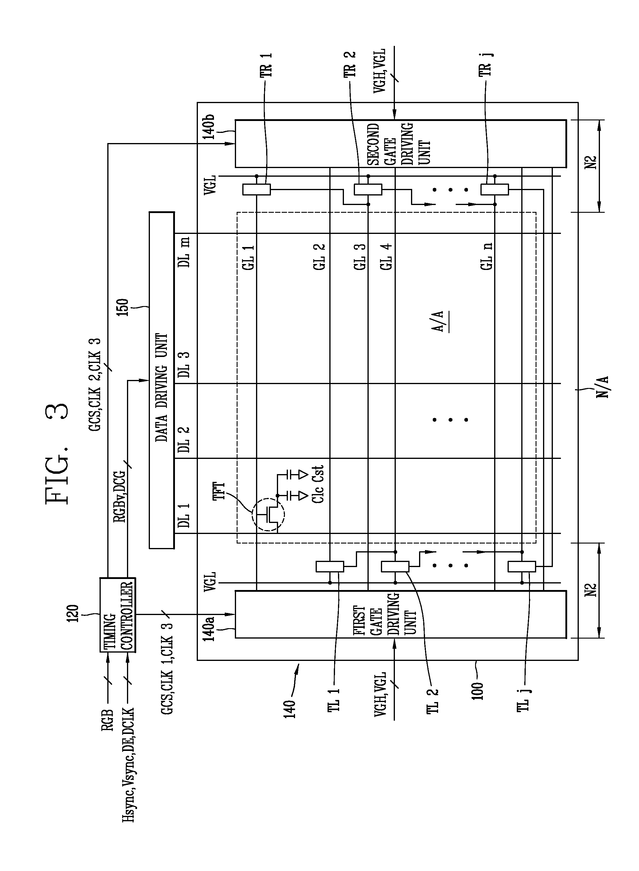
[0054]FIG. 3 is a view illustrating a liquid crystal display device and a driving unit thereof according to the present invention.

[0055]As illustrated in the drawing, a liquid crystal display according to the present invention may include a liquid crystal panel 100 configured to display an image, a timing controller 120 configured to receive a timing signal from an external system and generate various control signals, and gate and data driving units 140, 150 configured to control the liquid crystal panel 100 in correspondence to the control signals.

[0056]For the liquid crystal panel 100, a plurality of gate lines (GLs) and a plurality of data lines (DLs) are crossed with each other in a matrix form on a substrate using a glass to define a plurality of pixels at the crossed locations. Each pixel is provided with a thin-film transistor, a liquid crystal capacitor (Clc), and a storage capacitor (Cst), and all the pixels constitute one active area (A / A). An area in which pixels are not ...

second embodiment

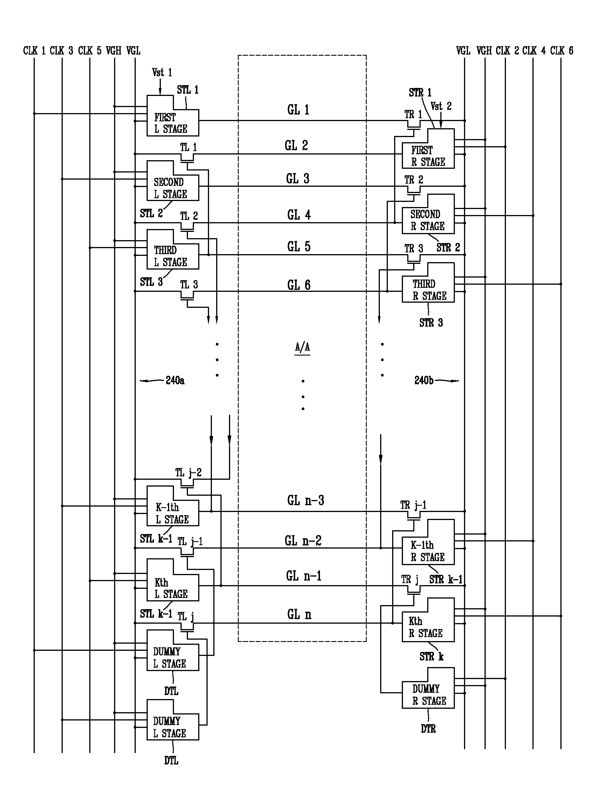
[0101]Hereinafter, a 6-phase drive dual GIP type liquid crystal display device and a driving unit thereof according to the present invention will be described with reference to the drawing.

[0102]FIG. 6 is a view illustrating the structure of a gate driving unit and a discharge circuit formed on a liquid crystal panel according to a second embodiment of the present invention.

[0103]As illustrated in the drawing, a second embodiment of the present invention may use 6-phase clock signals (CLK 1˜CLK 6) for more stable operation during the operation at 120 Hz, contrary to the foregoing first embodiment.

[0104]A liquid crystal display device according to a second embodiment of the present invention may include a liquid crystal panel 200 configured to display an image, a timing controller 220 configured to receive a timing signal from an external system and generate various control signals, and gate and data driving units 240, 250 configured to control the liquid crystal panel 200 in corresp...


PUM

PropertyMeasurementUnit
sizeaaaaaaaaaa
frequencyaaaaaaaaaa
voltageaaaaaaaaaa

Abstract

The present invention relates to a liquid crystal display device, and more particularly, to a gate-in-panel (GIP) type dual gate structure liquid crystal display device for minimizing a region occupied by a gate driving unit in the GIP structure liquid crystal display device in which the gate driving unit supplying a gate driving signal is formed on a liquid crystal panel to implement a narrow-bezel, and improving image quality deterioration due to signal delay. According to the present invention, the number of stages may be reduced through the structure of alternately outputting a gate driving voltage other than the structure of simultaneously outputting a gate driving voltage from two gate driving units in a dual GIP type liquid crystal display, thereby minimizing an area occupied by the gate driving unit.

Description

CROSS-REFERENCE TO RELATED APPLICATIONS[0001]This application claims the benefit of Korean Patent Application No. 10-2012-0043420, filed on Apr. 25, 2012, which is hereby incorporated by reference for all purposes as if fully set forth herein.BACKGROUND OF THE INVENTION[0002]1. Field of the Invention[0003]The present invention relates to a liquid crystal display device, and more particularly, to a gate-in-panel (GIP) type dual gate structure liquid crystal display device for minimizing a region occupied by a gate driving unit in the GIP structure liquid crystal display device in which the gate driving unit supplying a gate driving signal is formed on a liquid crystal panel to implement a narrow-bezel, and improving image quality deterioration due to signal delay.[0004]2. Description of the Related Art[0005]In recent years, cathode ray tubes or the like in the related art have been replaced by flat display devices in the electronic information display device field, and such flat disp...

Claims


Application Information

Patent Timeline
Patent Type & Authority Applications(United States)
IPC IPC(8): G02F1/133
CPCG02F1/13306G09G3/3677G09G3/3696G09G2300/0426G09G2310/0281G09G2310/0286G09G2310/08G09G3/36
Inventor LEE, JU-YOUNG
Owner LG DISPLAY CO LTD
Why Eureka
Try Eureka