Fuel cell using seawater electrolyzer, methods for producing caustic soda, ammonia, urea and PVC using the seawater electrolyzer and integrated system thereof

a technology of fuel cell and seawater, which is applied in the field of fuel cell system, can solve the problems of low efficiency, corrosion and damage of the cooling water intake site, and the vast amount of cooling water that power generation systems need

Inactive Publication Date: 2013-10-31
XFC
View PDF4 Cites 11 Cited by
  • Summary
  • Abstract
  • Description
  • Claims
  • Application Information

AI Technical Summary

Benefits of technology

[0015]In another embodiment of the present invention, the fuel cell may further include a heat exchanger for exchanging heat of first cooling water discharged from the power generation system or the chemical plant with heat of second cooling water entering the fuel cell, and a radiator using the second cooling water discharged from the fuel cell as a heat source, wherein the radiator is connected to the heat exchanger through a cooling water circulating pipe so that the second cooling water can be circulated through the fuel cell, the radiator and the heat exchanger. The fuel cell may further include a heat exchanger for exchanging heat of third cooling water discharged from the ammonia production plant and the urea production plant with heat of the second cooling water entering the fuel cell, and a radiator using the second cooling water discharged from the fuel cell as a heat source, wherein the radiator is connected to the heat exchanger through a cooling water circulating pipe so that the second cooling water can be circulated through the fuel cell, the radiator and the heat exchanger. I

Problems solved by technology

Power generation systems need a vast amount of cooling water.
The marine organisms entering the cooling water intake facility are usually adhered to and grow on various constituent sites of the cooling water intake facility, including the inner walls of the seawater channel, causing corrosion and damage to the sites of the cooling water intake facility.
This clogging causes low efficiency and failure of a cooling water pump, leading t

Method used


Image

  • Fuel cell using seawater electrolyzer, methods for producing caustic soda, ammonia, urea and PVC using the seawater electrolyzer and integrated system thereof
  • Fuel cell using seawater electrolyzer, methods for producing caustic soda, ammonia, urea and PVC using the seawater electrolyzer and integrated system thereof
  • Fuel cell using seawater electrolyzer, methods for producing caustic soda, ammonia, urea and PVC using the seawater electrolyzer and integrated system thereof

Examples


Embodiment Construction

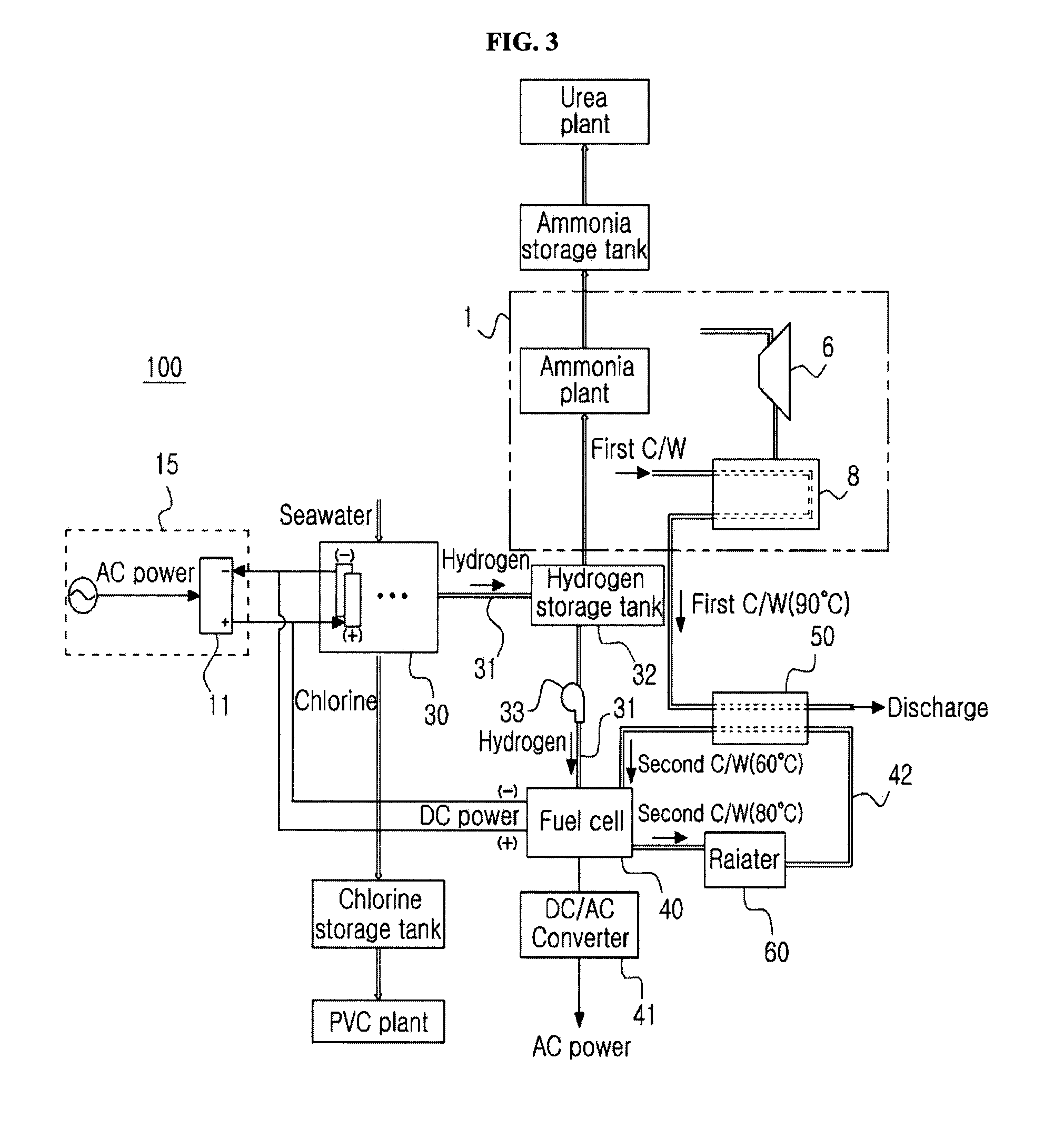
[0026]The present invention will now be described in more detail with reference to the accompanying drawings. The present invention provides an integrated system of a fuel cell based on a seawater electrolyzer, and chemical plants electrically connected to the fuel cell to receive power from the fuel cell. The integrated system of the present invention is characterized in that the fuel cell utilizes waste hydrogen from the seawater electrolyzer to generate electricity, and the chemical plants includes a plant for producing caustic soda in the seawater electrolyzer, a plant for producing PVC using chlorine from the seawater electrolyzer, a plant for producing ammonia using hydrogen from the seawater electrolyzer, and a plant for producing urea using the ammonia and carbon dioxide released from a neighboring power plant.

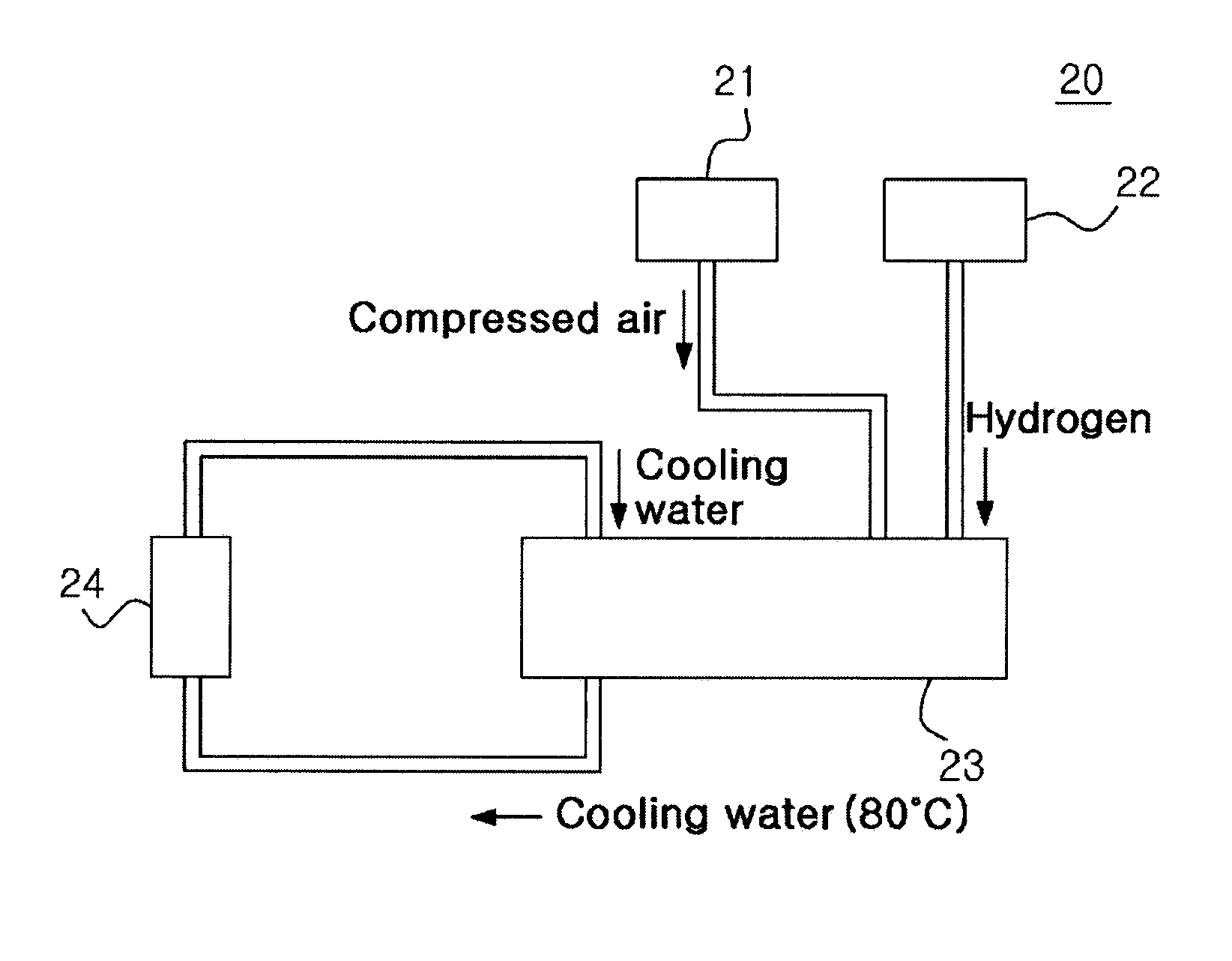
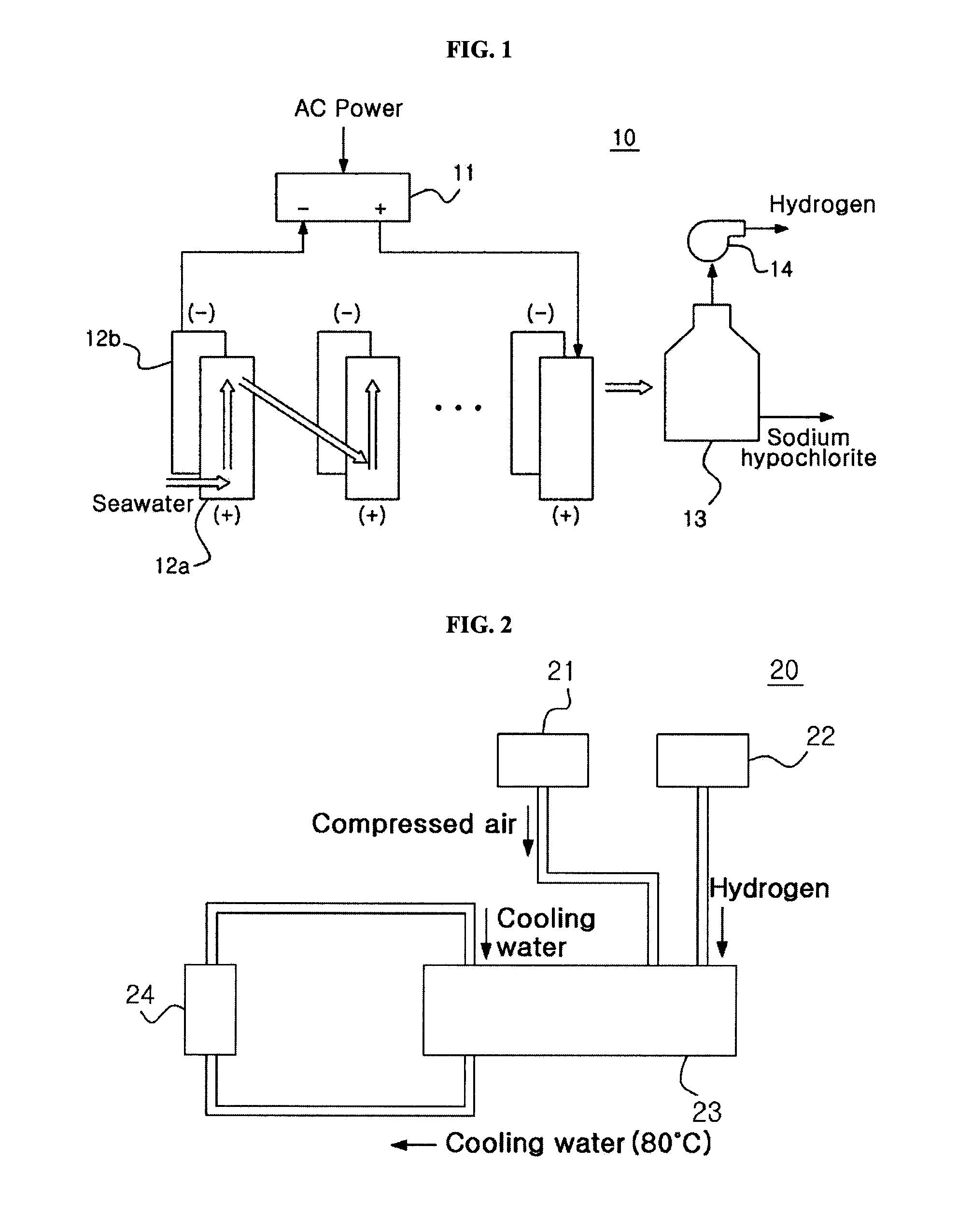
[0027]The constitution of the seawater electrolyzer 10 is illustrated in FIG. 1. Referring to FIG. 1, a rectifier 11 converting alternating current (AC) power to direc...


PUM

PropertyMeasurementUnit
Temperatureaaaaaaaaaa

Abstract

Provided are a fuel cell system using waste hydrogen from a seawater electrolyzer, a method for producing caustic soda using the fuel cell system and the seawater electrolyzer, a method for producing PVC using chlorine from the seawater electrolyzer, methods for producing ammonia and urea using hydrogen from the seawater electrolyzer, and an integrated system thereof. According to the integrated system, power generation by the fuel cell is combined with a seawater electrolysis process using a membrane, such as a Nafion membrane.

Description

CROSS-REFERENCE TO RELATED APPLICATIONS[0001]This application claims priority under 35 U.S.C. §119 to Korean Patent Application No. 10-2012-0044807 filed on Apr. 27, 2012, in the Korean Intellectual Property Office, the disclosure of which is incorporated herein by reference in its entirety.BACKGROUND[0002]1. Field of the Invention[0003]The present invention relates to a fuel cell system using waste hydrogen from a seawater electrolyzer, a method for producing caustic soda using the fuel cell system and the seawater electrolyzer, a method for producing PVC using chlorine from the seawater electrolyzer, methods for producing ammonia and urea using hydrogen from the seawater electrolyzer, and an integrated system thereof.[0004]2. Description of the Related Art[0005]Power generation systems need a vast amount of cooling water. To meet this need, seawater is commonly used as cooling water for power generation systems. Sedentary organisms such as shellfish (including mussels and clams) a...

Claims


Application Information

Patent Timeline
IPC IPC(8): H01M8/06
CPCH01M8/0656C25B1/04C25B15/08H01M2250/10Y02B90/10Y02E60/36Y02E60/50Y02P20/133Y02P70/50C08F14/06C25B1/26H01M8/06
Inventor LEE, JU-HYUNG
Owner XFC
Why Eureka
Try Eureka