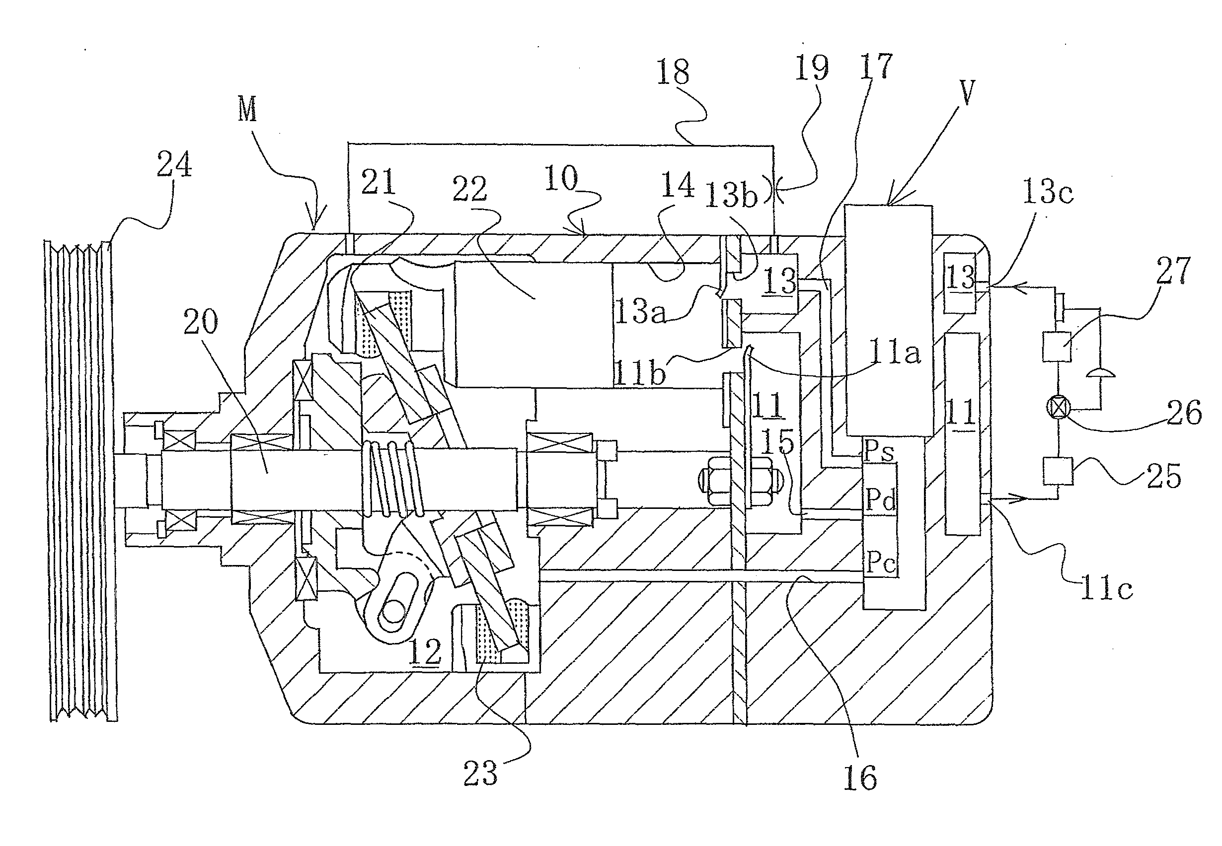
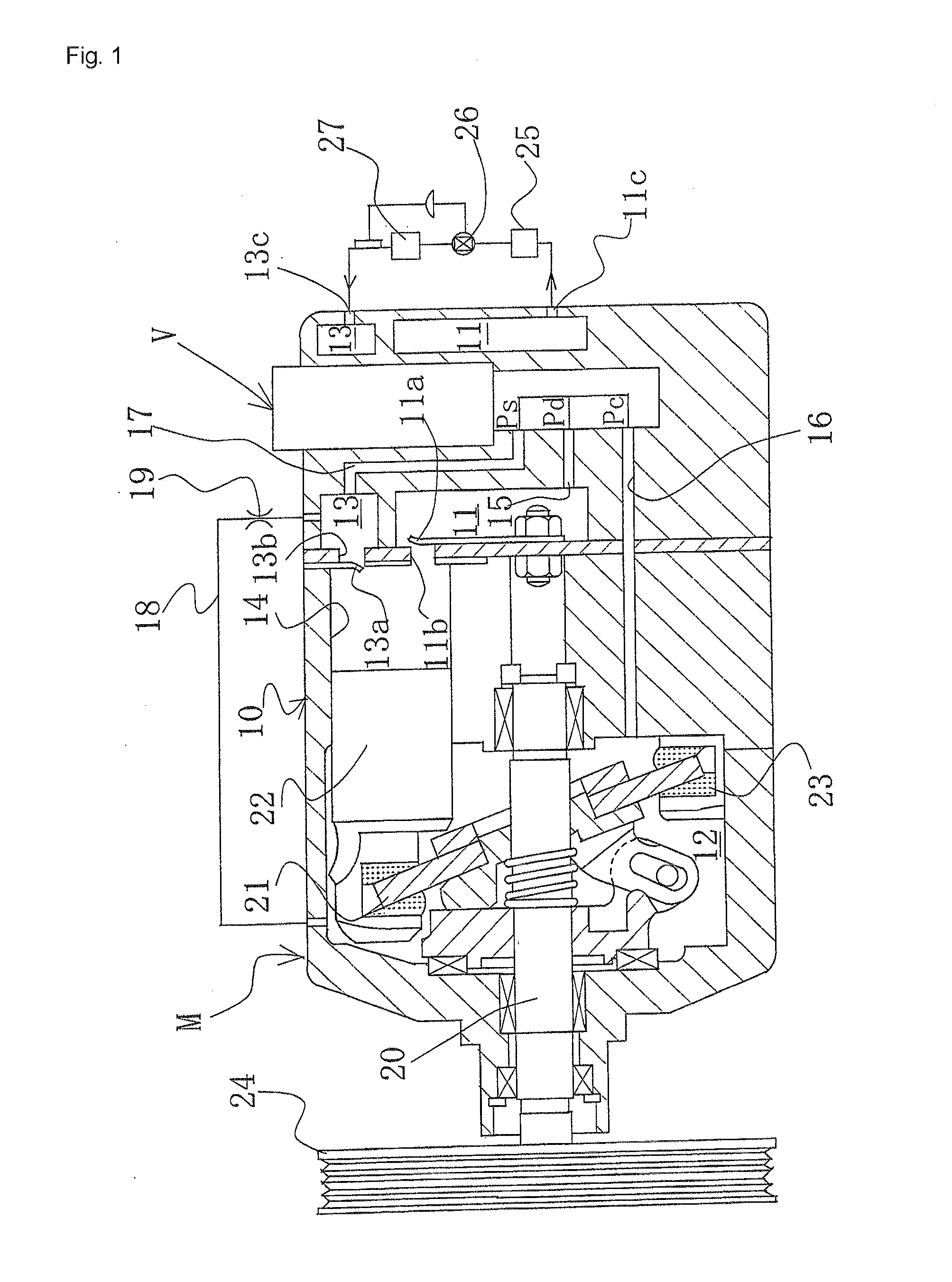
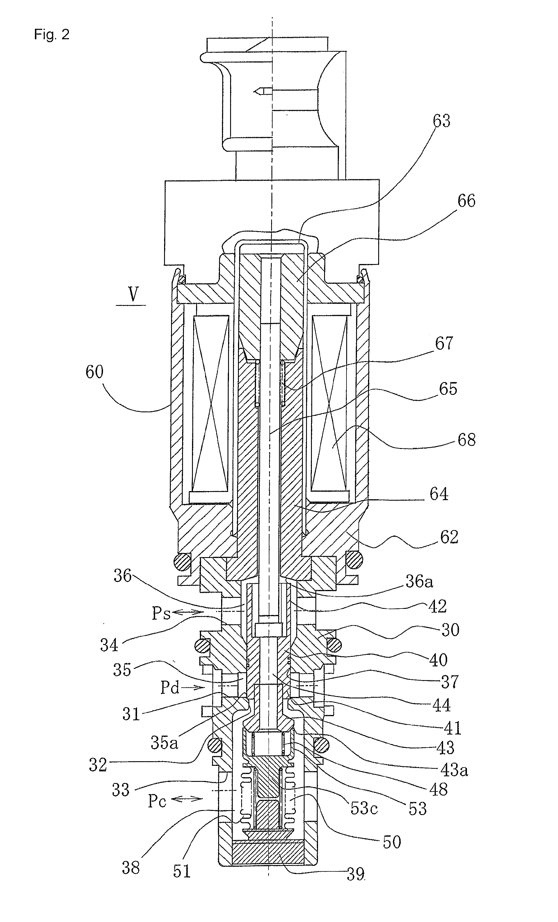
Capacity control valve

a technology of capacitive control valve and valve body, which is applied in the direction of valve operating means/release devices, machines/engines, positive displacement liquid engines, etc., can solve the problems of adversely affecting the control speed of the swash plate, the inability to change the seal diameter d ultimately, and the inability to manufacture and urging the urging means, etc., to achieve efficient utilization, facilitate the manufacture and urging force setting of the urging means, and increase the pitch of the coil

Active Publication Date: 2013-11-07
EAGLE INDS
View PDF8 Cites 34 Cited by
  • Summary
  • Abstract
  • Description
  • Claims
  • Application Information

AI Technical Summary

Benefits of technology

[0042]The present invention has advantageous effects such as those described below.
[0043](1) Providing an urging means for urging in the valve-opening direction between the adapter and the third valve part makes it possible to provide a capacity control valve in which the open area between the adapter and the third valve part can be increased and the valve-open state can be maintained until the suction pressure decreases further, the ability to drain the liquid refrigerant of the control chamber during starting of a variable-capacity compressor can be increased, and the swash plate control speed can be enhanced during normal control (between maximum-capacity operation and minimum-capacity operation) and minimum-capacity operation, without changing the control valve characteristics of the capacity control valve.
[0044](2) Through a configuration in which the urging means is formed from a coil spring, the manufacture and urging-force setting of the urging means are facilitated, and the flow of liquid refrigerant is not inhibited by increasing the pitch of the coil.
[0045](3) Through a configuration in which the urging means is disposed on an internal peripheral side of the adapter, the space inside the adapter can be efficiently utilized, and the adapter and the third valve part can be compactly formed.
[0046](4) Through a configuration in which the urging means is disposed on an external peripheral side of the adapter, the urging means can be easily attached and replaced.

Problems solved by technology

The seal diameter D ultimately cannot be changed, due to the limitation placed thereon by the bellows effective diameter.
A flow from the control chamber (crankcase) to the suction chamber therefore occurs, which adversely affects the swash plate control speed during control of the variable-capacity compressor.

Method used


Image

  • Capacity control valve
  • Capacity control valve
  • Capacity control valve

Examples


second embodiment

[0107]FIG. 5 is a sectional front view showing a second embodiment of the capacity control valve of the present invention.

[0108]In FIG. 5, reference numerals that are the same as those in FIG. 2 refer to the same members, and no detailed description of such members is given hereinafter.

[0109]In the second embodiment, a flange 45 extending through the entire circumference is provided on an outside surface positioned closer to the solenoid 60 than the end surface 47 of the third valve part 43, and a flange 54 extending through the entire circumference is also provided in the adapter 53 on a basal outside surface of the hollow cylindrical part 53a. The urging means 48 is installed between the flange 45 of the third valve part 43 and the flange 54 of the adapter 53, along the external periphery of the hollow cylindrical part 53a of the adapter 53, and acts in the valve-opening direction of the third valve part 43 and the adapter 53. The urging means 48 comprises a coil spring or other s...


PUM


Abstract

A capacity control valve for increasing the ability to drain liquid refrigerant from a control chamber during startup of a variable-capacity compressor without changing the control valve characteristics has a spring acting in the direction of valve opening provided between an adapter and a free end of a pressure-sensitive body in the extension and contraction direction thereof and having an annular seat surface, and a third valve part having an annular engaging surface for opening and closing a suction-side passage by engaging and disengaging with the seat surface of the adapter.

Description

TECHNICAL FIELD[0001]The present invention relates to a capacity control valve for variably controlling the capacity or pressure of a working fluid, and relates particularly to a capacity control valve for controlling the discharge amount of a variable-capacity compressor or the like used in an air conditioning system of an automobile or the like.BACKGROUND ART[0002]A swash plate variable-capacity compressor used in an air conditioning system of an automobile or the like is provided with a rotating shaft driven by the rotational power of an engine, a swash plate connected so that the inclination angle thereof with respect to the rotating shaft is variable, a compression piston connected to the swash plate, and other components, and by varying the stroke of the piston by varying the inclination angle of the swash plate, the discharge amount of refrigerant gas is controlled.[0003]The inclination angle of the swash plate can be continuously varied by appropriately controlling the press...

Claims


Application Information

Patent Timeline
Patent Type & Authority Applications(United States)
IPC IPC(8): B60H1/00
CPCB60H1/00485F04B27/1804F04B2027/1827F04B2027/1831Y10T137/7761F04B27/08F04B27/14
Inventor FUTAKUCHI, MASAYUKIFUKUDOME, KOHEIMORIWAKI, KENJIHAYAMA, MASAHIROKANZAKI, TOSHINORICHO, RYOSUKE
Owner EAGLE INDS
Why Eureka
Try Eureka