Free-space combining of laser beam radiation

a free-space and laser beam technology, applied in the field of diode laser beam combining technique, can solve the problems of high undesirable effects, increase in the number of combined emitters, and single-mode emission with diffraction-limited beam quality, and achieve the effect of reducing power consumption and generated heat, and high combined beam power density

Active Publication Date: 2013-11-07
DHPC TECH
View PDF3 Cites 4 Cited by
  • Summary
  • Abstract
  • Description
  • Claims
  • Application Information

AI Technical Summary

Benefits of technology

[0017]In view of the foregoing, one object of the present invention is to provide a semiconductor diode laser bar beam combining module that produces a high combined beam power density in the far field with a limited number of combined laser beams and a reduction in power consumption and generated heat.
[0019]It is still another object of the present invention is to provide a diode laser free-space beam combining and collimation module with a reduced axial length.

Problems solved by technology

In the fast axis direction the output beam from diode laser emitting apertures exhibits single mode emission with diffraction-limited beam quality.
While reduction in the power density due to the bar smile and component misalignments can be offset by an increase in the number of combined laser emitters, the larger number of emitters will also lead to an associated increase in the power consumption and the laser module power dissipation.
In applications with a limited amount of supplied power the increase in the number of combined emitters, as well as the increase in heat dissipation, is highly undesirable.

Method used


Image

  • Free-space combining of laser beam radiation
  • Free-space combining of laser beam radiation
  • Free-space combining of laser beam radiation

Examples


first embodiment

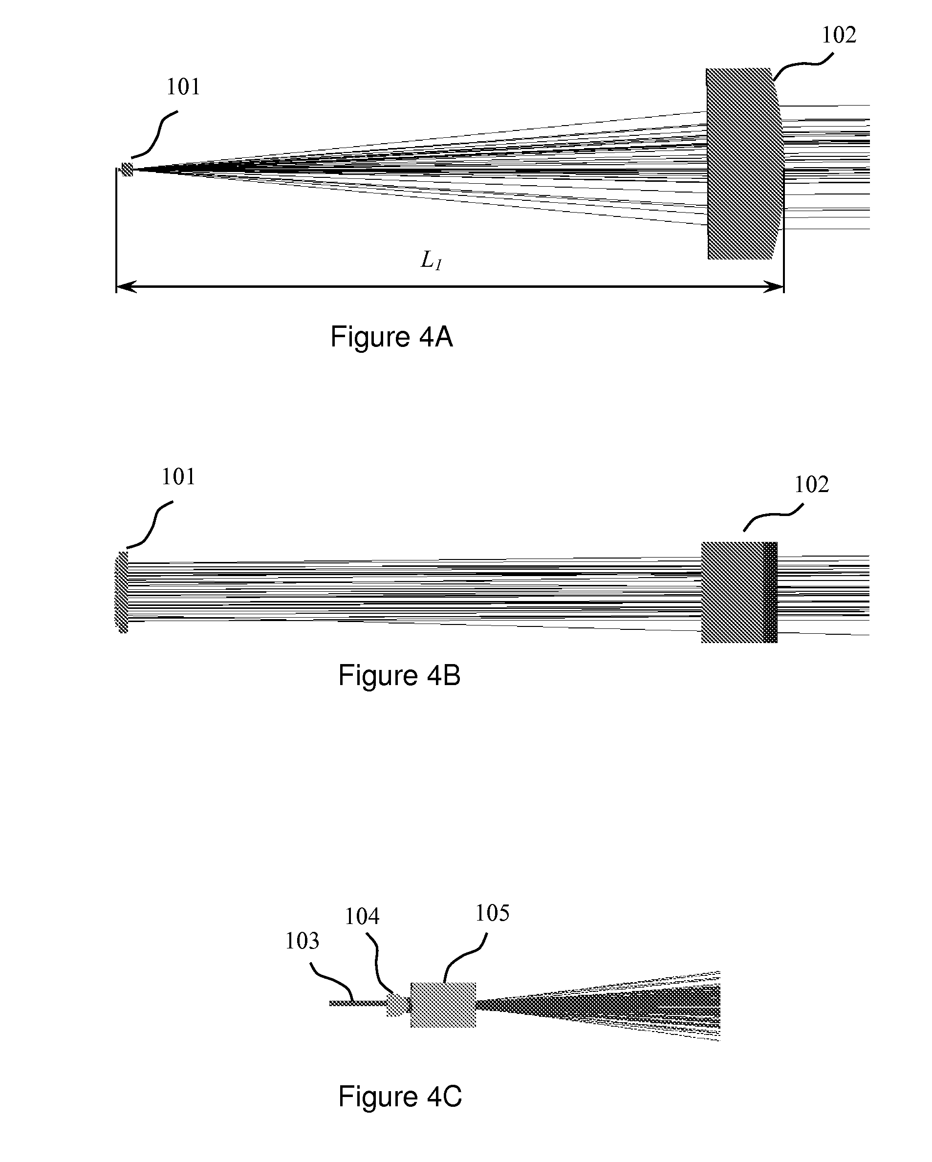
[0038]According to the present invention the required power density in the far field of the combined beam is achieved with a limited number of emitting diodes and a commensurate reduction in power consumption and heat dissipation by selecting appropriate focal lengths for the collimating optics, as well as the lateral spacing between the emitting apertures within the diode bar.

[0039]The far-field angular beam size θFF is defined as a combination of the diffraction term θFFDiffr and geometrical termθFFGeom:

θFF=θFFDiffr+θFFGeom   (1)

[0040]The diffraction term θFFDiffr represents the contribution to the angular beam size by diffraction effects on the optics apertures, and is proportional to the operating wavelength λ and is inversely proportional to the effective aperture size Deff:

θFFDiffr=λDeff(2)

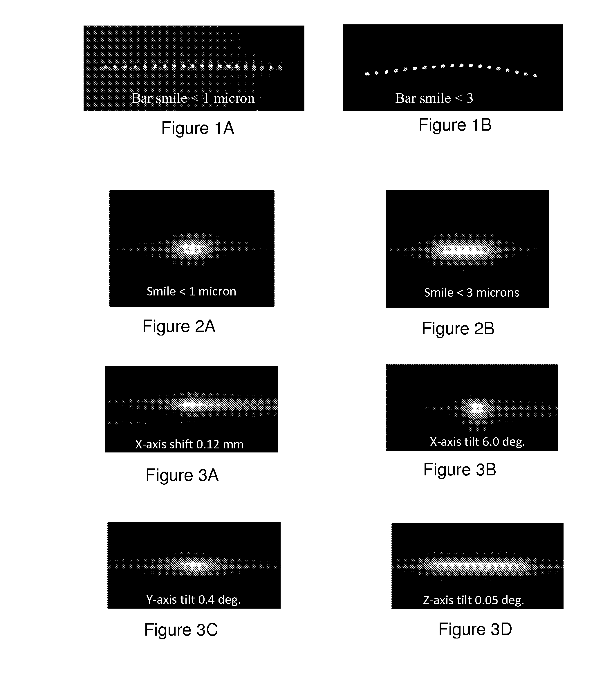
[0041]The second term θFFGeom represents the contribution to the far-field angular beam size due to misalignment effects and component imperfections. The geometrical beam divergence term in ...

second embodiment

[0053]Several laser applications require high combined collimated beam far field power density at the lowest consumed electrical power and heat dissipation levels within the module with a precisely controlled far field aspect ratio a. The beam aspect ratio a is defined as the ratio of the beam cross-sections in the two orthogonal lateral directions. Several applications may require the combined output laser beam to be square-shaped, with approximately equal beam divergences in the two orthogonal lateral directions and an aspect ratio α=1.

[0054]In the slow axis direction the output beam divergence is dominated by the geometrical divergence term. The far field beam divergence in the slow axis direction can de estimated as:

θSA=wSAfSA(5)

where wSA is the width of the individual emitter apertures in the slow axis direction, and fSA is the focal length of the cylindrical lens that collimates the combined output laser beam in a direction perpendicular to a junction plane after the beam tran...

third embodiment

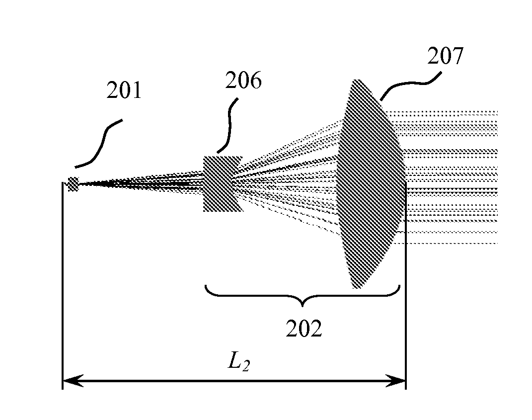
[0059]As discussed in connection with the previous embodiment, long focal length cylinder collimating lenses are employed after the beam transforming micro-optics to produce low diverging far field combined beams in the direction perpendicular to a junction plane. The long focal length of the cylindrical collimating lens after the beam transforming micro-optics leads to a significant increase in the axial size of the packaged laser module.

[0060]To reduce the axial module size while maintaining a low slow axis output beam divergence in accordance with the third embodiment of the present invention a composite collimating assembly after the beam transforming micro-optics is employed. The collimating assembly includes at least two cylindrical lenses, one with a negative optical power and one with a positive optical power. The collimating assembly may also include a mechanism to adjust the axial spacing between the positive and the negative lenses of the assembly. Adjustment of the axial...


PUM


Abstract

A diode laser beam combining apparatus for producing a high combined beam power density in the far field at reduced levels of power consumption and heat dissipation includes an array of semiconductor laser emitters arranged in a collinear manner with respect to each other and having an emitter pitch between about 0.7 mm and 2.5 mm. The apparatus also includes a cylindrical lens for collimating emitter beams generated by the array of laser emitters in a direction perpendicular to a junction plane of the laser emitters. The apparatus further includes a micro-optic array and a long focal length cylindrical lens. The micro-optic array is configured to perform a rotational transformation of the collimated emitter beams. The micro-optic array has a lateral spacing in a direction parallel to the junction plane of the laser emitters that matches the emitter pitch. The long focal length cylindrical lens collimates emitter beams in the direction perpendicular to the junction plane after passing through the micro-optic array.

Description

CROSS REFERENCE TO RELATED APPLICATION[0001]This application is a continuation of U.S. application Ser. No. 13 / 097,156, filed Apr. 29, 2011 entitled FREE-SPACE COMBINING OF LASER BEAM RADIATION, the application is hereby incorporated by reference in its entirety.FIELD OF THE INVENTION[0002]The present invention relates to a technique that performs free-space beam combining of several individual laser emitters. More specifically, it relates to a diode laser beam combining technique that is capable of producing high power density combined beams from a limited number of laser beams with reduced power consumption.BACKGROUND OF THE INVENTION[0003]Recent trends in laser technology development are characterized by the introduction of small size coherent emitters, such as fiber lasers, as well as high-power semiconductor diode lasers. High output beam power from a laser module is commonly achieved by combining several output beams from the individual emitters into a single output beam.[0004...

Claims


Application Information

Patent Timeline
Patent Type & Authority Applications(United States)
IPC IPC(8): G02B27/12
CPCG02B27/12G02B27/0961G02B27/0966G02B19/0057G02B19/0014G02B19/0061
Inventor SOSKIND, YAKOV G.GIFFORD, RICHARDALETTA, JOSEPH
Owner DHPC TECH
Why Eureka
Try Eureka