
Dye-sensitized solar cell based on indirect charge transfer

Active Publication Date: 2013-11-14
THE HONG KONG POLYTECHNIC UNIV
View PDF5 Cites 0 Cited by
  • Summary
  • Abstract
  • Description
  • Claims
  • Application Information

AI Technical Summary

Benefits of technology

The present invention provides a dye-sensitized solar cell that includes a unique electrode design with semiconductor nanoparticles and nanofibers. The electrode is sensitized with two different light absorption materials that have complementary light absorption bands, resulting in improved photon absorption and energy conversion efficiency. The method of producing the electrode includes dispersing semiconductor nanoparticles and nanofibers on a transparent conductive substrate, sensitizing the nanofibers with a first light absorption material, and depositing a second light absorption material on top of the first material in a shell structure. The technical effects of this invention include improved photon absorption, higher energy conversion efficiency, and improved stability and durability of the dye-sensitized solar cell.

Problems solved by technology

While the traditional ruthenium-based dyes exhibit relative broad adsorption spectrum, it has difficulty in further improving its Power Conversion Efficiency (PCE) due to its low molar extinction coefficients.
However, it has achieved only limited success to-date.
This is probably due to (i) inferior injection efficiency caused by intermolecular interactions between dyes; (ii) confined surface areas of the photoanode for dyes to be absorbed.
Considerable efforts have been made to solve these problems, one option is to separate the adsorption sites on TiO2, which means achieving the proper position of each dye on the desired site, however, there is difficulty in realizing such a concept.
Unfortunately, I3− in the electrolyte was found to partially quench the fluorescence of the donors, therefore only limited improvement in device performance can be achieved with such approach.

Method used


Image

  • Dye-sensitized solar cell based on indirect charge transfer
  • Dye-sensitized solar cell based on indirect charge transfer
  • Dye-sensitized solar cell based on indirect charge transfer

Examples


Embodiment Construction

[0031]The accompanying drawings, which are incorporated in and constitute a part of the specification, illustrate embodiments of the invention and, together with the description, serve to explain the principles of the invention.

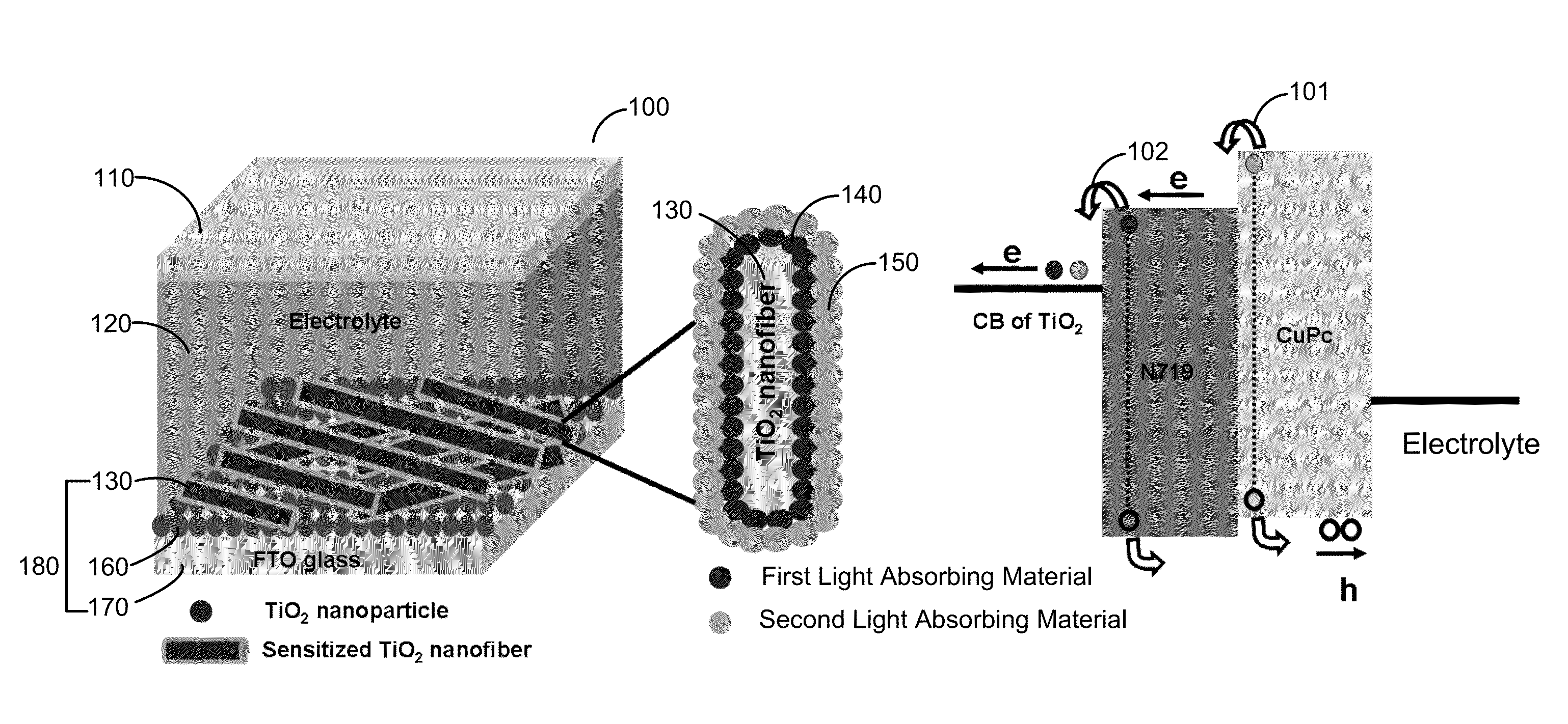
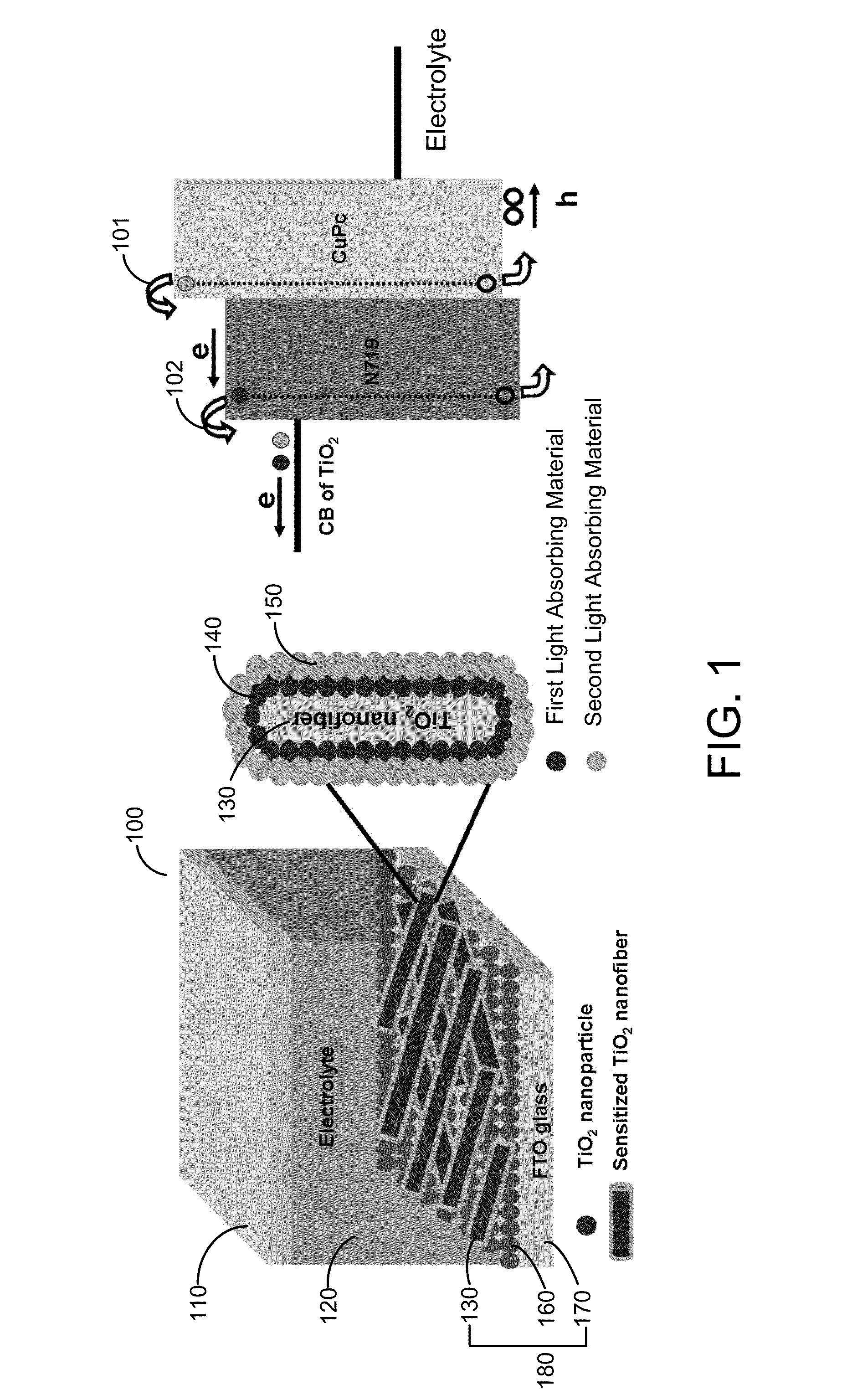
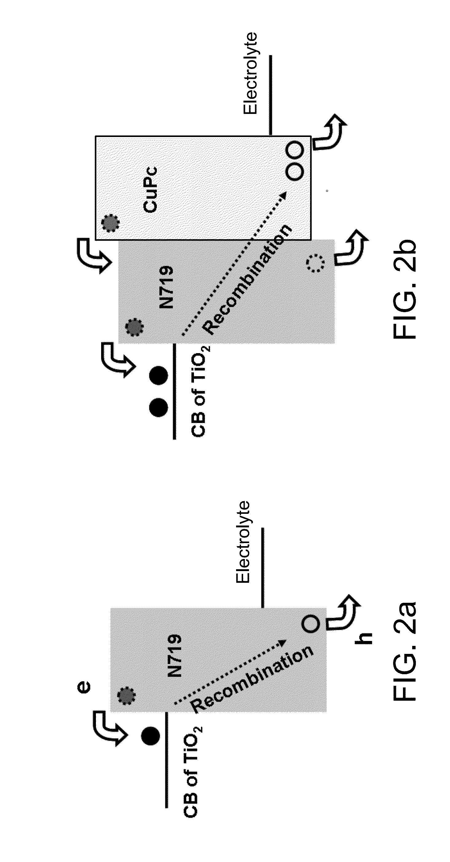
[0032]DSSC offers the potential of low-cost, high-efficiency photovoltaic device. However, conventional DSSC cannot utilize all of the photons of the visible solar spectrum and consequently the realized power conversion efficiency (PCE) is limited. The present invention discloses a core-shell photoanode, where a thin shell of infrared dye is deposited on the core of sensitized TiO2 nanofiber. In such architecture, photons are absorbed by the infrared dye and undergo charge transfer to the sensitizing dye, which broadens the absorption spectrum and suppresses the recombination process (electron back reaction and recombination with electrolyte ions). In one embodiment, ruthenium-based dye (N719) sensitized TiO2 nanofibers are wrapped by thin-shell of copper pht...


PUM


Abstract

A dye-sensitized solar cell that includes an electrode having a semiconductor nanoparticle layer dispersed on a transparent conductive substrate, a plurality of semiconductor nanofibers dispersed on the nanoparticle layer, a first light absorption material is attached to the plurality of semiconductor nanofibers in which the first light absorption material having a first light absorption bandwidth, and a second light absorption material deposited on the light absorption material of the plurality of semiconductor nanofibers, the second light absorption material having a second light absorption bandwidth complementary to the first light absorption bandwidth, a counter electrode includes a metal-coated transparent conductive substrate, and an electrolyte in contact with the near-infrared light absorption material and the counter electrode.

Description

BACKGROUND OF THE INVENTION[0001]1. Field of the Invention[0002]The present invention relates to a dye-sensitized solar cell that converts solar energy to electric energy, and more particularly, to dye-sensitized solar cells that include ultra-fine semiconductor fibers sensitized with more than one light absorption materials.[0003]2. Description of the Related Art[0004]Dye-sensitized solar cell (DSSC) is a non-conventional photovoltaic technology that attracted much attention due to its cost-effectiveness in harvesting solar energy with appealing properties such as flexibility, transparency, and adaptability in large-area devices. The operating principle of DSSC is illustrated in FIG. 12. Upon illumination, the dyes adsorbed onto the metal oxide semiconductor (usually TiO2) are sensitized to the exited state (S*) by light absorption right at the interface and they dissociate readily to create an electron-hole pair, with electrons subsequently injected into the conduction band of the...

Claims


Application Information

Patent Timeline
IPC IPC(8): H01L31/0224H01L31/18H01L51/44B82Y40/00B82Y99/00
CPCB82Y40/00Y02E10/542B82Y30/00H01L51/0078H01L51/0086H01G9/2063Y02P70/50H10K85/311H10K85/344H01G9/2059H01L31/18
Inventor LEUNG, WALLACE WOON-FONGYANG, LIJUN
Owner THE HONG KONG POLYTECHNIC UNIV
Learn More