Ion exchange membrane method electrolytic cell

a technology electrolysis cell, which is applied in the direction of electrolysis process, electrolysis components, climate sustainability, etc., can solve the problems of increasing the electrolysis voltage, achieve easy adjustment, reduce the electric energy consumption, and avoid the effect of ion exchange membrane breakag

Active Publication Date: 2013-11-14
TOSOH CORP +1
View PDF6 Cites 9 Cited by
  • Summary
  • Abstract
  • Description
  • Claims
  • Application Information

AI Technical Summary

Benefits of technology

[0021]As illustrated in FIG. 1, the ion exchange membrane method electrolytic cell of the present invention has a cell structure such that a coil cushion (4) is arranged between an electrical conductive plate (2) and a cathode (3). By the coil cushion (4), the electrical energy consumption can be reduced. Further, the impact resilience of the coil cushion (4) can be easily adjusted so as to obtain a contact pressure of the desired extent, therefore, a uniform contact pressure is applied from via the coil cushion (4) between the cathode (3) and the ion exchange membrane (5). Thus, breakage of the ion-exchange membrane (5) occurring due to an excessive contact pressure can be prevented over a long period.
[0022]The electrical conductive plate (2) as used in the electrolytic cell of the present invention is made of a non-perforated plate, gas generated from the cathode (3) forms a stream violently rising along the coil cushion (4). The stream of gas is accompanied by liquid electrolyte, therefore, the liquid electrolyte also violently rises. Simultaneously the liquid electrolyte forms a stream violently flowing down between the non-perforated electrically conductive plate (2) and the partition (1). Consequently supply of liquid electrolyte to the ion exchange membrane (5) is enhanced, and the concentration of the liquid electrolyte is not reduced, and elevation of electrolysis voltage with time and reduction of current efficiency with time can be minimized.

Problems solved by technology

The above-mentioned modified ion exchange membrane method electrolytic cell has a problem such that the leaf spring-retaining member is apt to be distorted in operation by the pressure whereby the ion exchange membrane is occasionally spaced away from the cathode which leads to increase in the electrolysis voltage.

Method used


Image

  • Ion exchange membrane method electrolytic cell
  • Ion exchange membrane method electrolytic cell
  • Ion exchange membrane method electrolytic cell

Examples


example 1

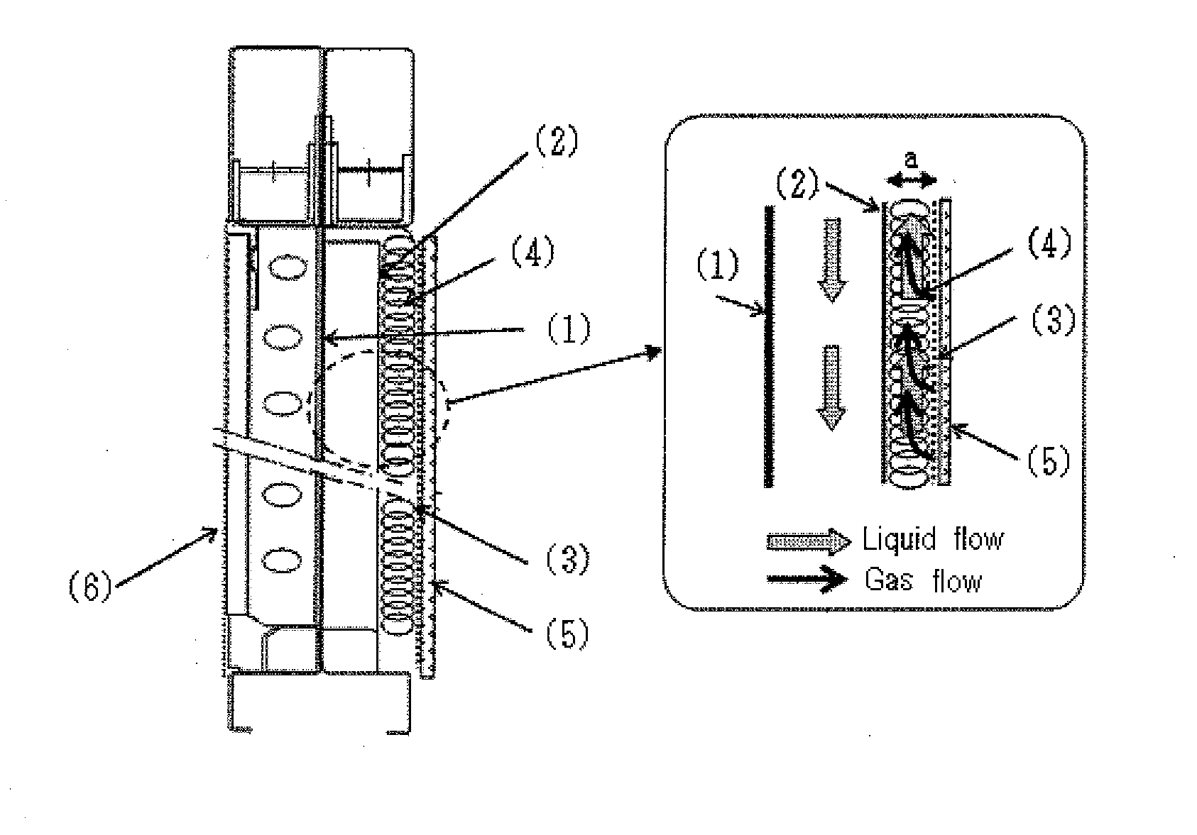
[0078]An ion exchange membrane method electrolytic cell having a structure as illustrated in FIG. 1 was assembled, wherein a coil cushion (4) was arranged between a non-perforated electrically conductive plate (2) and a cathode (3).

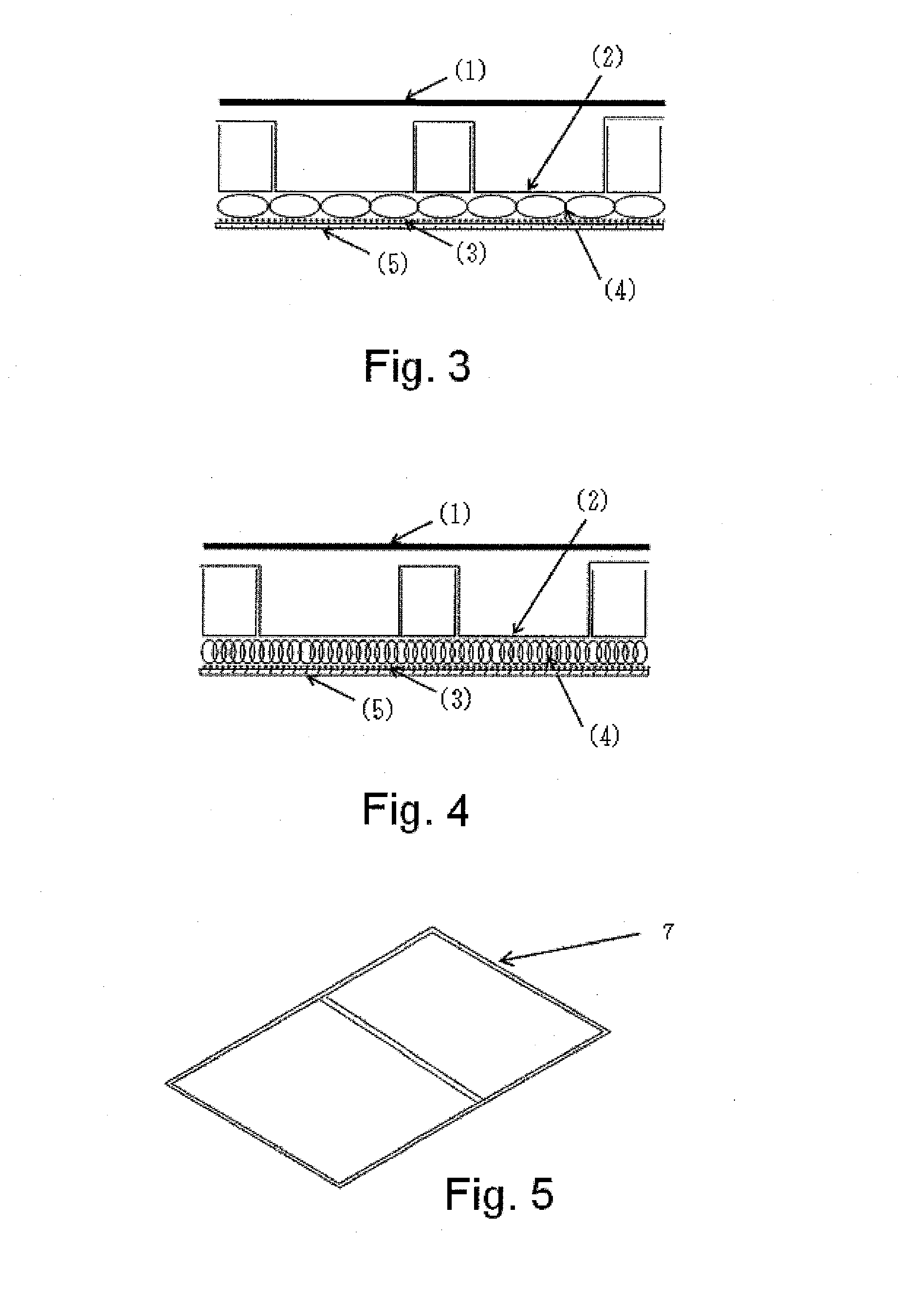
[0079]The coil cushion (4) used was made as follows. A metal frame (7) having a structure as illustrated in FIG. 5 was made from a nickel wire rod having a diameter of 1.2 mm. A metal coil having a coil diameter of 8.5 mm and comprised of a nickel wire having a diameter of 0.1 mm was made by a roll press. The metal coil (8) was wound around the metal frame (7) as illustrated in FIG. 6 at a winding number of 60 times per dm2. A coil cushion (4) was made from the metal coil (8) wound around the metal frame (7) as illustrated in FIG. 7. The coil cushion (4) was arranged between the non-perforated electrically conductive plate (2) and the cathode (3) as illustrated in FIG. 1.

[0080]The coil cushion (4) had a coil density of 3.0 g / dm2, and a coil thickness of 2...

example 2

[0089]By the same procedures and conditions as mentioned in Example 1, an ion exchange membrane method electrolytic cell apparatus having the same structure as mentioned in Example 1 was assembled and electrolysis of sodium chloride was conducted. An electrode coated with a platinum-nickel catalyst used as the cathode was prepared from an expanded metal substrate made of nickel having a length of 1400 mm in the short way direction and a length of 1200 mm in the long way direction. The expanded metal substrate was comprised of nickel strands having a strand width (width of cut) of 1.0 mm, a strand thickness (metal plate thickness) of 1.0 mm, and had a short way of 4.0 mm, a long way of 8.0 mm, and a percent open area of 46%. Other procedures and conditions remained the same.

[0090]The electrolysis voltage was measured. The electrolysis voltage was maintained at approximately 3.05 V, thus, 0.05 V higher than that as measured in Example 1.


PUM

PropertyMeasurementUnit
contact pressureaaaaaaaaaa
thicknessaaaaaaaaaa
thicknessaaaaaaaaaa

Abstract

An ion-exchange membrane method electrolytic cell comprising a coil cushion arranged between a conductive plate and a cathode in a cathode chamber, and further an ion-exchange membrane arranged in contact with the cathode. The conductive plate is not perforated, and the coil cushion is arranged so that its axial direction is in agreement with the vertical direction of electrolytic cell. Preferably the coil cushion is made of a metal coil and has an impact resilience of 7-17 kPa. The cathode preferably has supported electrode catalyst and is made of an expanded metal with strands of 0.1-1.0 mm width and 0.1-1.0 mm thickness, and having SW of 0.5-5.0 mm and LW of 1.0-10 mm, and 48-60% open area. The electrolytic cell is energy-saving, and damage thereof can be avoided over a long period, and elevation of voltage and reduction of current efficiency with time can be minimized.

Description

TECHNICAL FIELD[0001]This invention relates to a novel zero gap-type ion exchange membrane method electrolytic cell having a cell structure wherein an anode, an ion exchange membrane and a cathode are arranged in close contact with each other, which is used in electrolysis industry typically including electrolysis of alkali chloride.[0002]The ion exchange membrane method electrolytic cell of the present invention has a structure such that a coil cushion is arranged as a cushion arranged between a rib and a cathode within a cathode chamber instead of the spring retaining member as used in the conventional electrolytic cell. By using the coil cushion, the cathode of a mesh form and the ion exchange membrane can be placed in more close contact with each other, and enhanced voltage reducing effect can be exhibited.BACKGROUND ART[0003]The ion exchange membrane method electrolysis industry represented by the alkali chloride electrolysis plays an important role as a primary material indust...

Claims


Application Information

Patent Timeline
Patent Type & Authority Applications(United States)
IPC IPC(8): C25B9/08C25B9/19C25B9/23
CPCC25B9/08C25B1/26C25B11/03Y02P20/20Y02P20/10C25B9/65C25B9/19
Inventor SUEMOTO, HIROKISADAHIRO, FUMIONOMURA, TSUYOSHISAKAMOTO, KENJIKODAMA, YOSHIYUKI
Owner TOSOH CORP
Why Eureka
Try Eureka