Method and apparatus for manufacturing perpendicular magnetic recording medium

a manufacturing method and magnetic recording technology, applied in the field of magnetic recording medium manufacturing methods and equipment, can solve the problems of affecting reading or writing bits, reducing the coercivity of the first magnetic layer, so as to facilitate demagnetization of the magnetic layer, the effect of high coercivity

Inactive Publication Date: 2013-11-14
IZA
View PDF0 Cites 1 Cited by
  • Summary
  • Abstract
  • Description
  • Claims
  • Application Information

AI Technical Summary

Benefits of technology

[0024]According to the present invention, demagnetization is performed with the substrate temperature being high, i.e., the coercivity of the first magnetic layer being reduced by heating the substrate. Hence, demagnetization is enabled by applying a further smaller magnetic field, thereby facilitating demagnetization of the magnetic layer with a high coercivity.

Problems solved by technology

Advancement of the high-densification of HDDs brings about a disadvantage that magnetically recorded data is erased by heat generated around such data.
In order to enable a writing on a medium having a high coercivity, however, it is necessary to increase the magnetic field available to the magnetic head, but the available magnetic fields to the magnetic head are limited so far.
Energy assisted magnetic recording media are not currently being manufactured in high volume, but the manufacturing thereof is not considered to be significantly different from that of conventional perpendicular magnetic recording medium except for more involved heating and cooling requirements.
The large magnetic domains with the same magnetization direction in the medium adversely affect the reading or writing bits.
Hence, it is difficult to perform the demagnetization process while controlling a distance between the magnetic recording medium and the apparatus.
Moreover, there are other disadvantages such that the apparatus becomes complex and the costs increase.

Method used


Image

  • Method and apparatus for manufacturing perpendicular magnetic recording medium
  • Method and apparatus for manufacturing perpendicular magnetic recording medium
  • Method and apparatus for manufacturing perpendicular magnetic recording medium

Examples


first embodiment

(2) First Embodiment

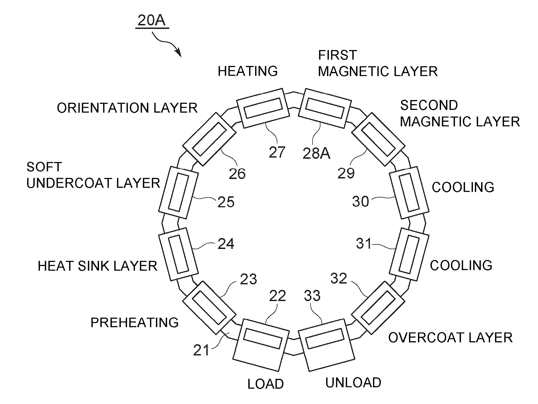
[0054]Next, an explanation will be given of a manufacturing apparatus 20A of the perpendicular magnetic recording medium 11 (hereinafter, referred to as the “manufacturing apparatus”) according to the first embodiment of the present invention. The manufacturing apparatus 20A illustrated in FIG. 3 includes a transfer system 21, a load lock chamber 22, a preheating chamber 23, a heat-sink-layer formation chamber 24, a soft-magnetism-undercoat-layer formation chamber 25, an orientation-layer formation chamber 26, a heating chamber 27, a first-magnetic-layer formation chamber 28A, a second-magnetic-layer formation chamber 29, a first cooling chamber 30, a second cooling chamber 31, an overcoat-layer formation chamber 32, and an unload chamber 33. The manufacturing apparatus 20A is capable of manufacturing the perpendicular magnetic recording medium 11 having multilayer films on both sides of the substrate 1. The respective chambers are disposed annularly, are connect...

second embodiment

(3) Second Embodiment

[0092]Next, an explanation will be given of a manufacturing apparatus according to a second embodiment. The same component as that of the first embodiment will be denoted by the same reference numeral, and the explanation thereof will be omitted. The manufacturing apparatus of this embodiment differs from the first embodiment that such a manufacturing apparatus is provided with a demagnetization heating chamber 42A.

[0093]A manufacturing apparatus 20C illustrated in FIG. 10 includes the transfer system 21, the load lock chamber 22, the preheating chamber 23, the heat-sink-layer formation chamber 24, the soft-magnetism-undercoat-layer formation chamber 25, the orientation-layer formation chamber 26, the heating chamber 27, a first-magnetic-layer formation chamber 28C, the demagnetization heating chamber 42A, the second-magnetic-layer formation chamber 29, the first cooling chamber 30, the overcoat-layer formation chamber 32, and the unload chamber 33, and is capab...

third embodiment

(4) Third Embodiment

[0114]Next, an explanation will be given of a manufacturing apparatus according to a third embodiment. The same component as that of the first embodiment will be denoted by the same reference numeral, and the explanation thereof will be omitted. The manufacturing apparatus of this embodiment differs from the first embodiment that the magnetic field generator is a magnet unit for sputtering provided in the first-magnetic-layer formation chamber 28C.

[0115]As illustrated in FIG. 15, a manufacturing apparatus 20E includes the heating chamber 27, the first-magnetic-layer formation chamber 28C, and the second-magnetic-layer formation chamber 29. The manufacturing apparatus 20E differs from the first embodiment that no magnetic field generator is separately provided like the above-explained embodiment.

[0116]As illustrated in FIG. 16, the first magnetic-layer-formation chamber 28C has the pair of first targets 58 provided at both sides of the substrate 1 with the substra...


PUM

PropertyMeasurementUnit
Curie temperatureaaaaaaaaaa
diameteraaaaaaaaaa
temperatureaaaaaaaaaa

Abstract

A method and an apparatus for manufacturing a perpendicular magnetic recording medium are provided which can easily demagnetize a magnetic layer with a high coercivity. The method includes: forming a magnetic layer on a substrate; applying magnetic fields parallel to the surface of the magnetic layer having a coercivity reduced below the intensity of said magnetic field by heating of the magnetic layer; and removing said magnetic field.

Description

BACKGROUND OF THE INVENTION[0001]1. Field of the Invention[0002]The present invention relates to a method and an apparatus for manufacturing a magnetic recording medium having a magnetic layer with a high coercivity, and more specifically, a magnetic recording medium having a function of demagnetizing a magnetic layer.[0003]2. Description of the Related Art[0004]Magnetic Hard Disk Drives (HDDs) typically include a magnetic disk medium and a magnetic head. In general, the magnetic disk medium is a perpendicular magnetic recording medium having high coercivity polycrystalline magnetic films with perpendicular magnetic anisotropy on a magnetic disk surface. The magnetic head includes a magnetoresistive reader and a high magnetic moment writer. Data is written in the magnetic disk medium, and data recorded in the disk medium is read.[0005]A perpendicular magnetic recording medium includes a substrate, a thin film layer having non-magnetic and magnetic layers, an overcoat typically made ...

Claims


Application Information

Patent Timeline
Patent Type & Authority Applications(United States)
IPC IPC(8): G11B5/84
CPCG11B5/84G11B5/66G11B5/852
Inventor ABARRA, NOEL
Owner IZA
Why Eureka
Try Eureka