
Frangible fixing screw

a fixing screw and screw technology, applied in the field of fixed screws, can solve the problems of excessive weakened frangible sections, fractures in the tissue and/or the implant, and a zone that is particularly vulnerable to fatigue stress, and achieve the effect of increasing the fatigue resistance of zirconia

Inactive Publication Date: 2013-11-14
ZDA ZIRCONIA DEVEMENT & APPL
View PDF7 Cites 21 Cited by
  • Summary
  • Abstract
  • Description
  • Claims
  • Application Information

AI Technical Summary

Benefits of technology

The invention is a screw that has a special breaking or frangible zone under the head of the screw, which means that if the frangible zone breaks, the screw can still keep its normal shape and function. This design reduces stress concentration and allows the screw to play its part without affecting its fatigue strength. The screw can be made from yttria-stabilized zirconia, which increases its fatigue resistance. This makes it suitable for use as an implantation device for superstructures where the whole is free of metal.

Problems solved by technology

That is because in such conditions, the difference between the elastic modulus of the bone and that of the implant leads to elastic deformation incompatibility stresses between the bone and the implant, which remain limited in usual living conditions but can become great in extreme situations and lead to a break in the tissue and / or the implant.
The hardness of the implant renders its removal problematic once it has been integrated into the bone, making it indispensable to retain the integrity of the implant in all circumstances, including these extreme circumstances.
As the price of such a safety, making a groove that is too deep would create an excessively weakened frangible section and a zone that would be particularly vulnerable to fatigue stress.
The problem is even more critical when the screw is made in material such as a ceramic material that does not have a significant capacity of accommodation by plastic deformation, so as to slow or to stop the progression of cracks, and where the fatigue resistance ratio in relation to static resistance is low.

Method used


Image

  • Frangible fixing screw
  • Frangible fixing screw
  • Frangible fixing screw

Examples


Embodiment Construction

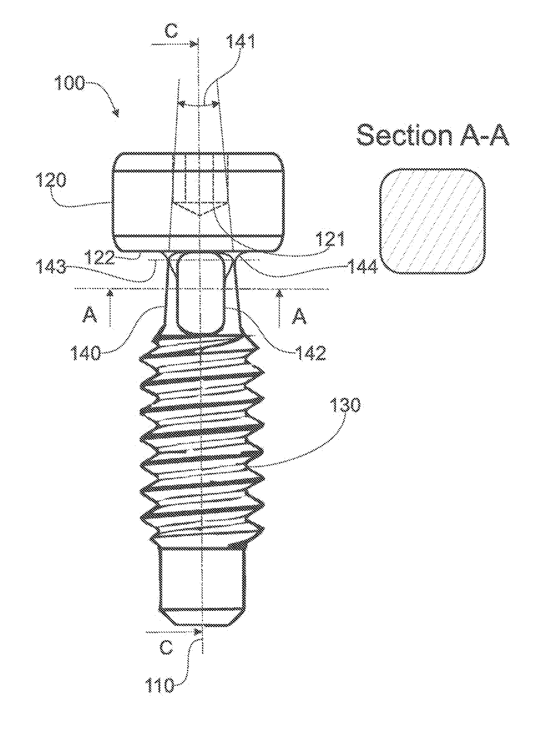
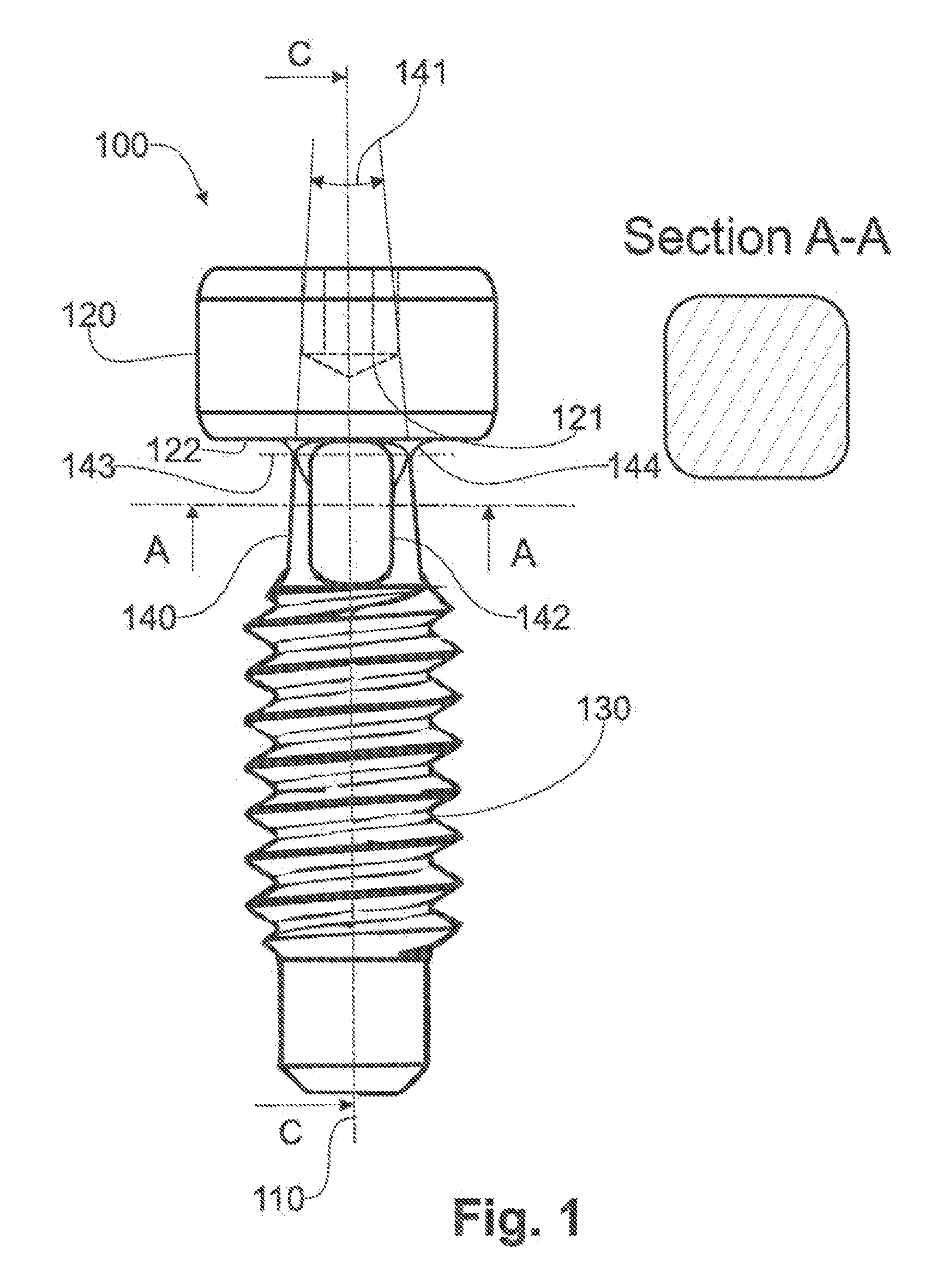
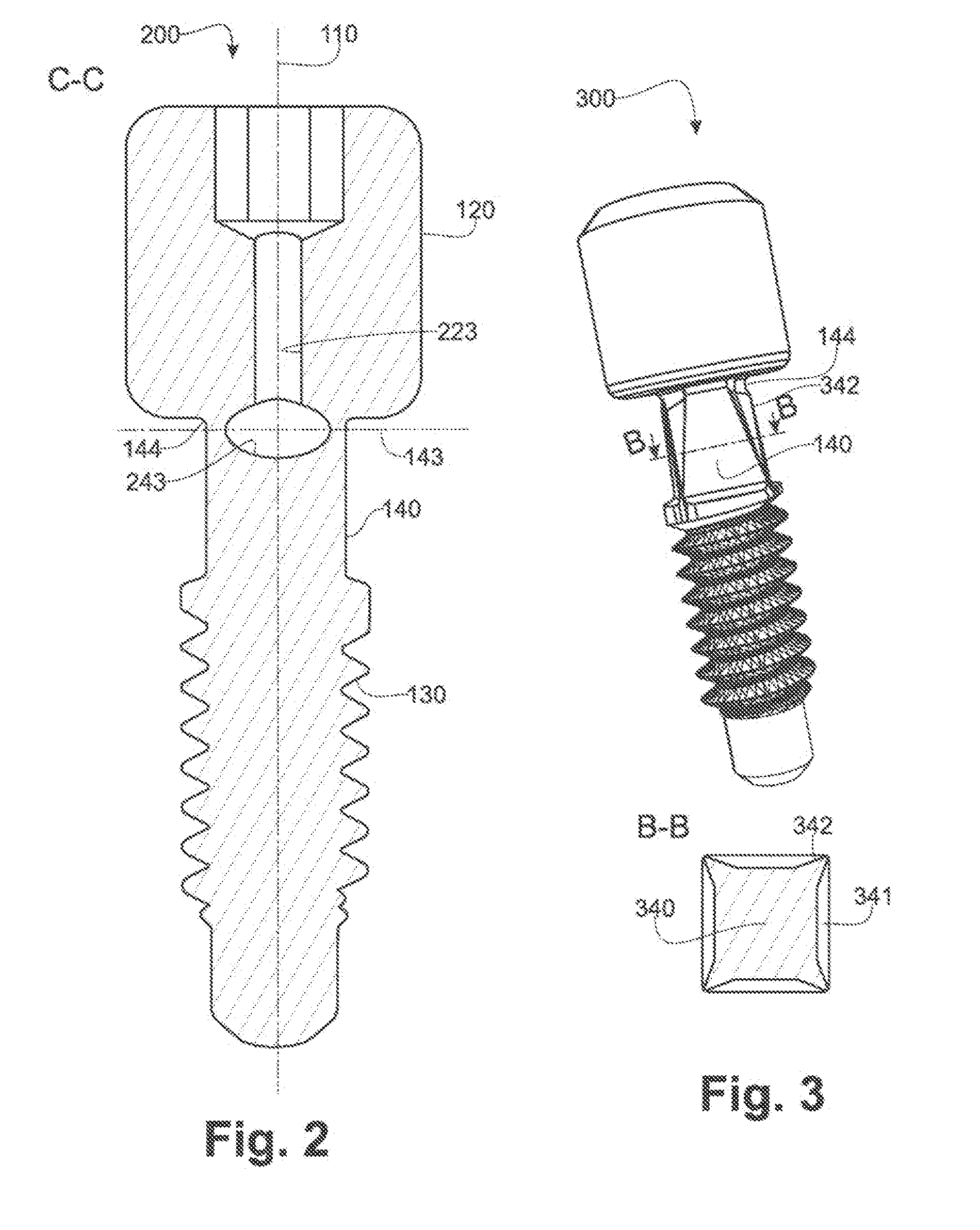
[0031]In FIG. 1 according to a first exemplary embodiment, the fixing screw (100) of the invention comprises a screw head (120) and a threaded part (130) that are coaxial along a longitudinal axis (110). The screw head (120) comprises a driving shape (121), for example in the shape of a hexagonal recess. The other end of the head (120), near the thread (130), comprises a bearing surface (122), which, in this exemplary embodiment, is a flat surface but which may be conical, spherical or have any other shape capable of creating a contact surface in order to allow tightening on an adapted complementary surface on a superstructure. The threaded part (130) of the screw is inserted in the tapping of an intra-osseous implant, after said implant has been implanted in the receiving tissue. The bearing surface (122) of the screw head (120) and the thread (130) thus cooperate to hold a superstructure such as an abutment in place on said implant by tightening.

[0032]Between the bearing surface (...


PUM

PropertyMeasurementUnit
conical angleaaaaaaaaaa
stress concentration coefficient Ktaaaaaaaaaa

Abstract

The invention relates to a screw, particularly for attaching a superstructure to an intra-osseous implant. The extends along a longitudinal axis and comprises a head and a thread. The head comprises a bearing surface configured to cooperate with a bearing surface of the superstructure to hold the superstructure in position. The thread is configured to engage with a tapping to tighten the bearing surfaces of the superstructure and the screw. Between the bearing surface and the thread, the screw comprises a safety portion. The safety portion comprises a driving shape and a frangible section at the connection between the safety portion and the head of the screw, so that the driving shape remains attached to the thread if the frangible section breaks.

Description

RELATED APPLICATIONS[0001]This application is a §371 application from PCT / EP2011 / 074331 filed Dec. 30, 2011, which claims priority from French patent application Ser. No. 11 / 00145 filed Jan. 18, 2011, each of which is herein incorporated by reference in its entirety.TECHNICAL FIELD OF INVENTION[0002]The invention relates to a frangible fixing screw. Such a screw is generally designed for the biomedical industry. It is particularly adapted for attaching a superstructure to an intra-osseous implant, particularly a periodontal implant. It is more specifically but not exclusively adapted to the installation of superstructures on such implants when they are made of a ceramic material, particularly zirconia. In one particularly advantageous application, this invention makes it possible to use a screw that is itself made of a ceramic material, particularly yttria-stabilized zirconia. The screw of the invention can also be used as a permanent or temporary intra-osseous implant, in particula...

Claims


Application Information

Patent Timeline
Patent Type & Authority Applications(United States)
IPC IPC(8): A61B17/86
CPCA61B17/8605A61C8/005A61C8/0068
Inventor GOURLAOUEN-PREISSLER, JEANNINEBUSSON, BERTRAND
Owner ZDA ZIRCONIA DEVEMENT & APPL
Learn More