Left Heart Assist Device and Method

a technology for assisting devices and left heart, which is applied in the field of intravascular blood circulation enhancement apparatus, intravascular blood circulation enhancement system and method, and can solve problems such as death, end stage heart failure, and a tendency to worsen rather than heal

Active Publication Date: 2013-11-14
SYNTACH AG
View PDF9 Cites 59 Cited by
  • Summary
  • Abstract
  • Description
  • Claims
  • Application Information

AI Technical Summary

Benefits of technology

[0011]Embodiments of the invention take advantage of an improved understanding of left ventricular pump action and the close relationship between the Coronary Sinus (CS), the Great Cardiac Vein (GCV) and the Mitral valve (MV). Embodiments of the invention are providing movement of the CS and the GCV and thereby the MV along the long axis of the left ventricle (LV) towards and / or away from the heart apex, in synchrony with the cardiac cycle. In some embodiments energy is provided for this assisting movement. The here described embodiments of permanent implants do not take over or replace the remaining left ventricular pump function, they rather augment, improve, enhance or support the remaining natural pump function by means of an at least partly increased up and / or down movement of the mitral valve that works as a blood displacement or propulsion piston, when it is closed during the systole.
[0015]The downwards movement of the mitral valve is in a healthy human up to approximately 2 centimetres. The downwards movement accelerates the blood column away from the left atrium and towards the aortic valve in a continuous movement. By means of MRI technology one is able to virtually mark separate pixels inside the blood column and follow their movement. It is possible to show that the blood column flows more or less continuously from the left atrium to the ascending aorta without ever stopping. The blood column is accelerated by the mitral valve piston moving up and down along the cardiac long axis, opening every time it takes a new scoop of blood in an upward movement to the atrium, and closing just before moving back toward the apex.
[0016]The inventor of the present application realized that the location of the Coronary Sinus (CS) and the Great Cardiac Vein (GCV), very close to the mitral valve, can be utilized for enhancement of the left ventricular pump function. For instance a downwards movement of the mitral valve substantially along the long axis of the left ventricle may be supported. By actively moving, or supporting a still existing natural cardiac movement of, the CS and the GCV downwards towards the apex one simultaneously can move the mitral valve in the same direction.
[0038]This additional transversal controlled movement may in some embodiments include moving the lateral LV wall in the heart in a reciprocating movement during systole towards an inter-ventricular septum of the heart and during diastole away from an inter-ventricular septum for assisting the pump action of the heart along the short axis of a LV of a heart.

Problems solved by technology

A peculiarity of heart cells is that they do not regenerate after damage or cell death, thus conditions have a tendency to worsen rather than heal after heart cell damage.
End stage of long standing high blood pressure may also cause end stage heart failure.
CHF is a progressive untreatable, disabling and finally a deadly condition.
However, due to the limited number of suitable organs only 2500 transplants are done yearly in the US.
However, these devices are still based on complex designs and are very invasive to install in the patient.
Failure in operation of the device is fatal.
In addition, major open heart surgery is still necessary to install and connect these devices to the left ventricle cavity and the aorta by means of large vascular grafts.
The mentioned devices have almost exclusively been used as a bridge to a heart transplant due to high frequency of complications, high mortality and limited durability.
Their use has also been limited because of high prices of up to 150 000 $ only for the device.
None of the devices for permanent implant described are feasible for minimal invasive catheter based insertion, on the contrary, they all involve major open heart surgery.

Method used


Image

  • Left Heart Assist Device and Method
  • Left Heart Assist Device and Method
  • Left Heart Assist Device and Method

Examples


Embodiment Construction

[0064]Specific embodiments of the invention will now be described with reference to the accompanying drawings. This invention may, however, be embodied in many different forms and should not be construed as limited to the embodiments set forth herein; rather, these embodiments are provided so that this disclosure will be thorough and complete, and will fully convey the scope of the invention to those skilled in the art. The terminology used in the detailed description of the embodiments illustrated in the accompanying drawings is not intended to be limiting of the invention. In the drawings, like numbers refer to like elements.

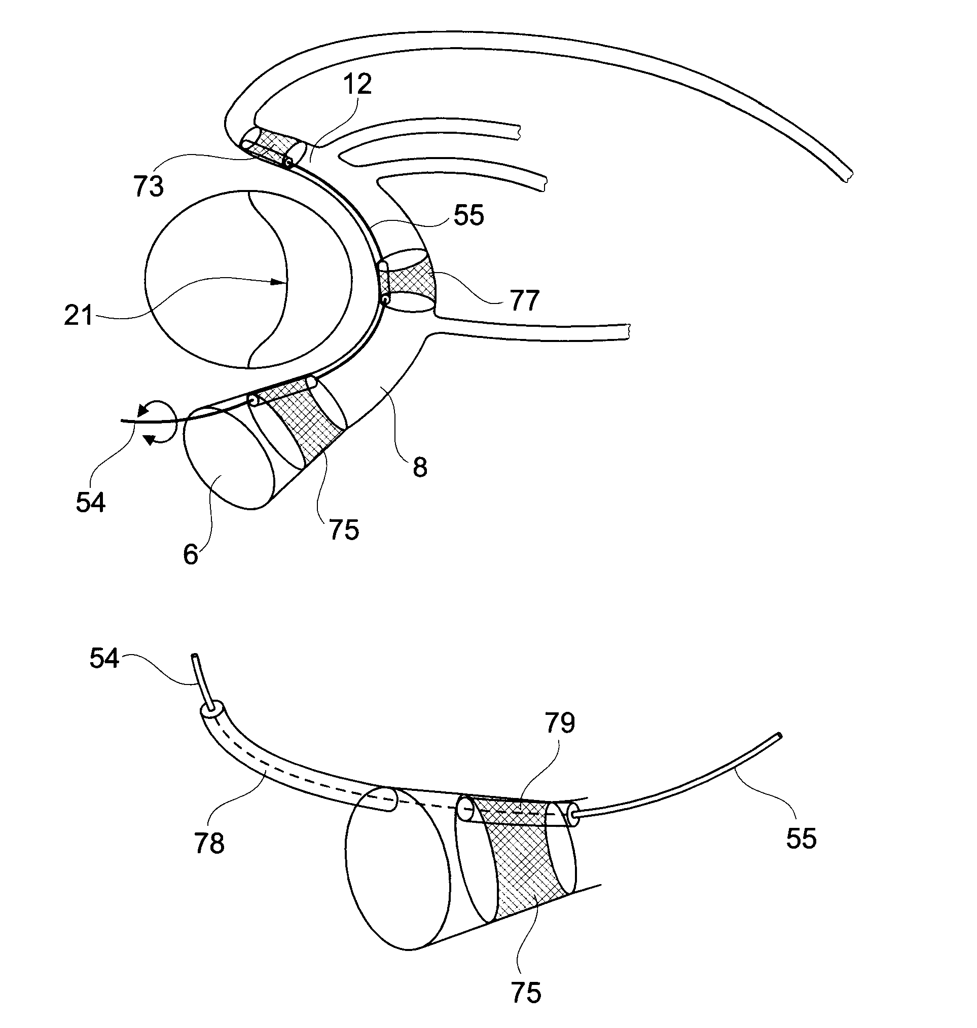
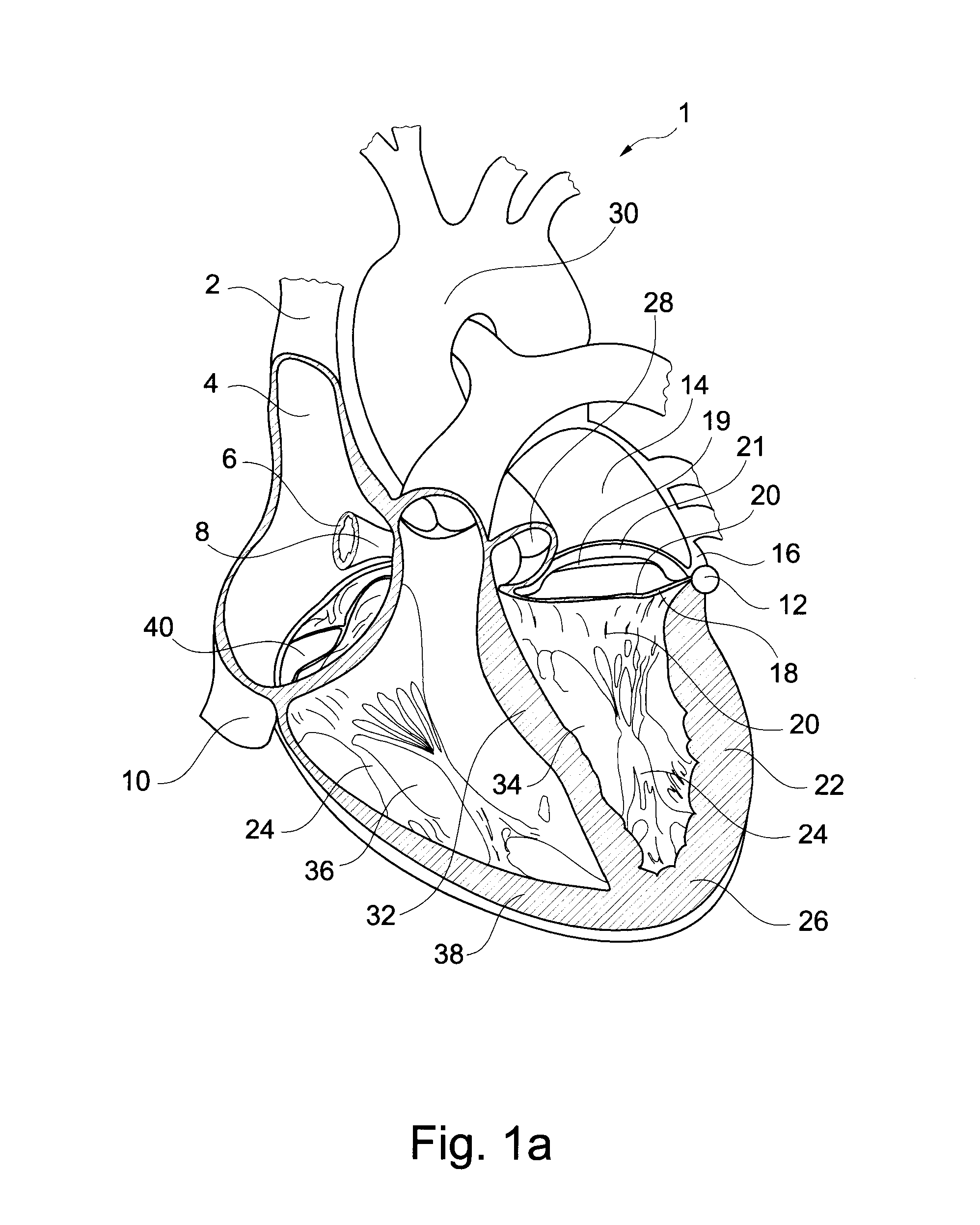
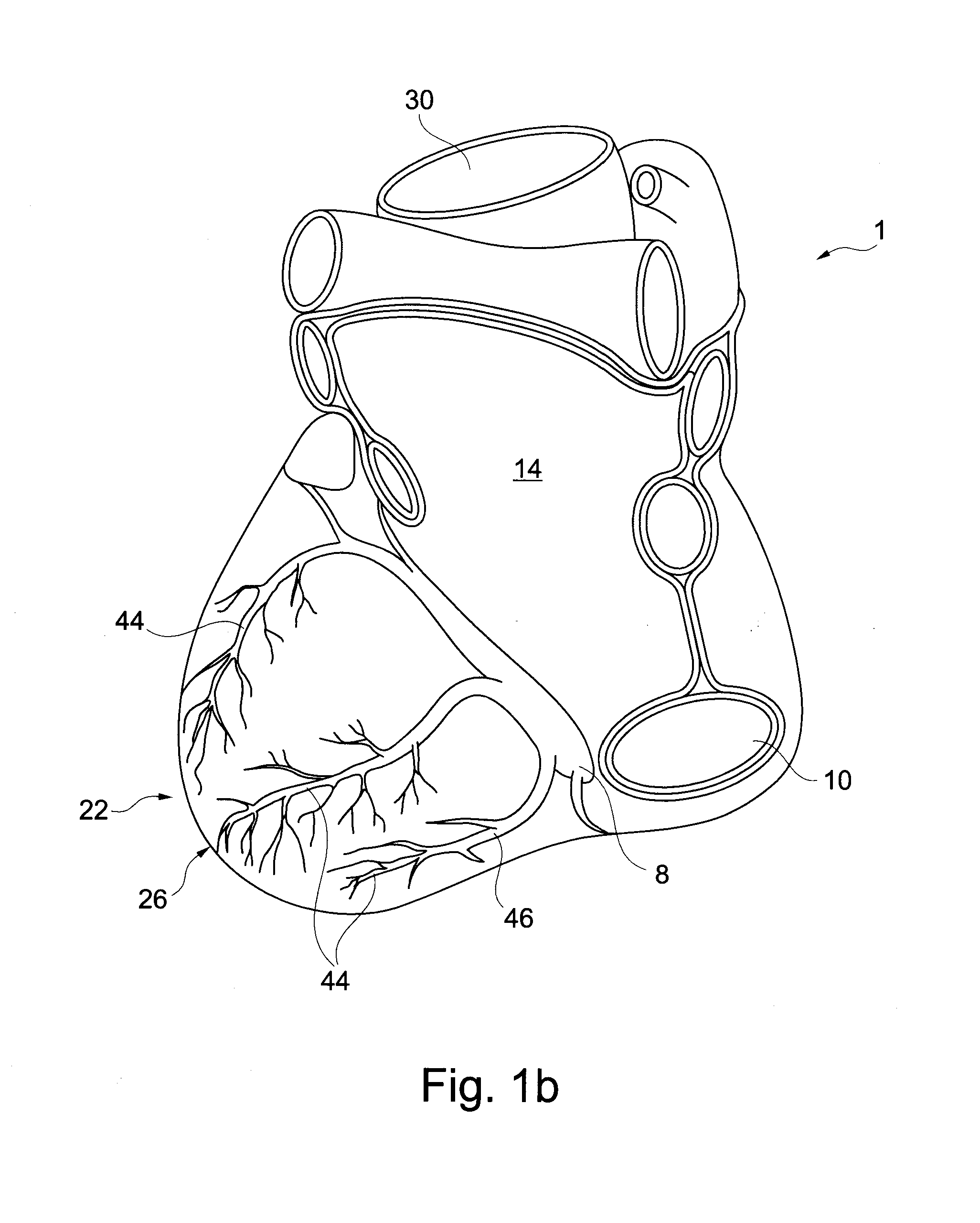
[0065]Embodiments of the invention take advantage of new discoveries of left ventricular pump action and the close relationship between the Coronary Sinus (CS), the Great Cardiac Vein (GCV) and the Mitral valve (MV). Embodiments are by means of external power able to provide a movement of the CS and the GCV and thereby the MV along the long axis of the left ve...


PUM


Abstract

A device, a kit and a method is presented for permanently augmenting the pump function of the left heart. The mitral valve plane is assisted in a movement along the left ventricular long axis during each heart cycle. The very close relationship between the coronary sinus and the mitral valve is used by various embodiments of a medical device providing this assisted movement. By means of catheter technique an implant is inserted into the coronary sinus, the device is augmenting the up and down movement of the mitral valve and thereby increasing the left ventricular diastolic filling when moving upwards and the piston effect of the closed mitral valve when moving downwards.

Description

RELATED APPLICATIONS[0001]This application is a continuation of U.S. patent application Ser. No. 13 / 122,710 filed Oct. 18, 2011 entitled A Device, A Kit And A Method For Heart Support, which is the U.S. National Phase of and claims priority to International Patent Application No. PCT / SE2011 / 050337, International Filing Date Mar. 25, 2011, entitled A Device, A Kit And A Method For Heart Support, which claims priority to U.S. Provisional Application Ser. No. 61 / 317,619 filed Mar. 25, 2010, and Swedish application Serial No. SE1050282-1 filed Mar. 25, 2010, both entitled Device, A Kit And A Method For Heart Support, all of which are hereby incorporated herein by reference.FIELD OF THE INVENTION[0002]The present invention relates to an intra-vascular blood circulation enhancing apparatus, a system for intra-vascular blood circulation enhancement and a method for enhancing left ventricular pump function of a patient. The present invention may specifically be used to enhance the pump func...

Claims


Application Information

Patent Timeline
Patent Type & Authority Applications(United States)
IPC IPC(8): A61F2/24A61M60/135A61M60/268A61M60/441A61M60/531A61M60/554
CPCA61F2/2451A61F2/2442A61M1/1068A61M1/10A61M60/289A61M60/495A61M60/476A61M60/515A61M60/861A61M60/865A61M60/187A61M60/191A61M60/148A61M60/40A61M60/857A61M60/135A61M60/441A61M60/531A61M60/554A61M60/268A61F2/24A61H31/004A61H31/006
Inventor SOLEM, JAN OTTO
Owner SYNTACH AG
Why Eureka
Try Eureka