Method and apparatus for charging multiple energy storage devices

a technology for energy storage devices and charging methods, applied in the direction of capacitors, battery/fuel cell control arrangements, transportation and packaging, etc., can solve the problems of unfavorable, unfavorable, and unfavorable, and achieve the marginal decrease in charging time. the effect of marginally increasing the charge tim

Active Publication Date: 2013-11-21
GENERAL ELECTRIC CO
View PDF7 Cites 57 Cited by
  • Summary
  • Abstract
  • Description
  • Claims
  • Application Information

AI Technical Summary

Benefits of technology

[0011]According to one aspect of the invention, an electric vehicle includes a controller configured to receive sensor feedback from a high voltage storage device and from a low voltage storage device, compare the sensor feedback to operating limits of the respective high and low voltage storage device, determine, based on the comparison a total charging current to the high voltage storage device and to the low voltage storage device and a power split factor of the total charging current to the high voltage device and to the low voltage device, and regulate the total power to the low voltage storage device and the high voltage storage device based on the determination.
[0012]In accordance with another aspect of the invention, a method of managing an energy storage system for an electric vehicle includes receiving sensor feedback from a high voltage energy storage device of the electric vehicle, comparing the sensor feedback from the high voltage energy storage device to an operating limit specific to the high voltage energy storage device, receiving sensor feedback from a low voltage energy storage device of the electrical vehicle, comparing the sensor feedback from the low voltage energy storage device to an operating limit specific to the low voltage ener

Problems solved by technology

Although such an optimization often can be adequate to provide a maximum overall rate of charging to the combination of devices being charged, such a charging scheme does not take into account additional factors such as the overall implications to the life of the devices themselves that are being charged, their temperature limits, and the like.
That is, although energy storage devices may be physically capable of receiving a high rate of charge in order to minimize charging time of all devices, it may not be desirable to do so if the long-term cost to one or more of the devices is a drop in life.
In other words, th

Method used


Image

  • Method and apparatus for charging multiple energy storage devices
  • Method and apparatus for charging multiple energy storage devices
  • Method and apparatus for charging multiple energy storage devices

Examples


case 1

[0056]

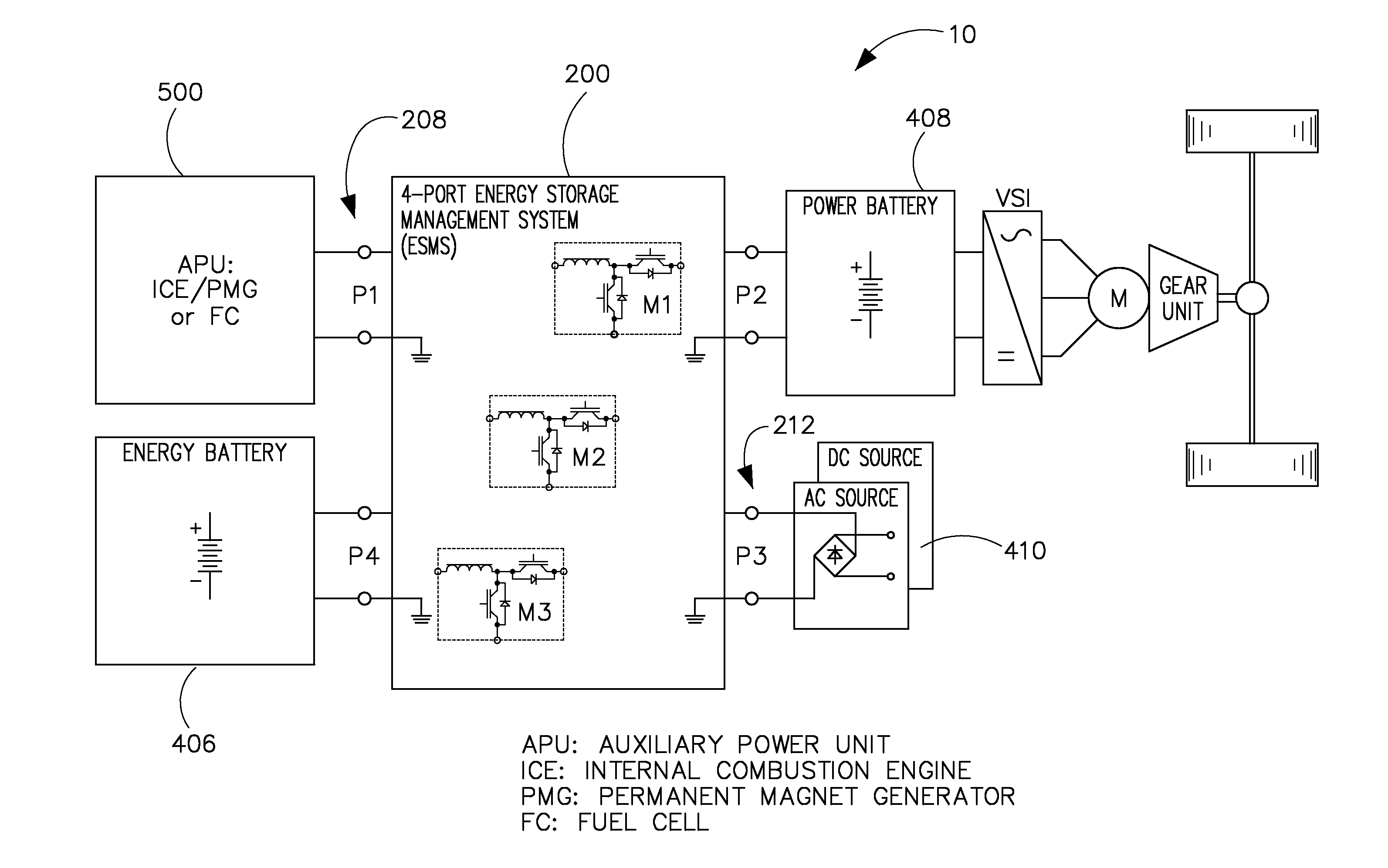
[0057]Input voltage at port 3 212 is higher than battery voltage at port 1 208. In this case module 2 204 operates in buck mode and the current ILB in LU is regulated. Contactors K3 216 and K1 218 are closed, while M 224, K2 220 and K4 222 (UPOS) are open.

case 2

[0058]

[0059]Input voltage at port 3 212 is lower than battery voltage at port 1 208. In this case contactors K3 216, M 224 and K4 222 (UPOS) are closed, while K1 218 and K2 220 are open. Module 2204 is inactive (M2 is permanently on), module 1 202 operates in boost mode to boost the low input voltage up to some higher level. Module 3 206 bucks this voltage back to the set voltage of the energy battery at port 1 208. The current ILC in LW is controlled in a closed loop fashion.

[0060]Thus, FIGS. 5 and 6 illustrate different charging scenarios that may be implemented using ESMS 200 of FIG. 3, illustrating as well the direction of current flow corresponding to the charging arrangement illustrated. However and as stated, ESMS 200 may be used in multiple configurations. Different energy storage types and chargers may be connected to ESMS 200 according to embodiments of the invention, as illustrated in FIG. 7 as a table 300. That is, exemplary charging scenarios 1-5 302 include functions 3...


PUM


Abstract

An electric vehicle includes a controller configured to receive sensor feedback from a high voltage storage device and from a low voltage storage device, compare the sensor feedback to operating limits of the respective high and low voltage storage device, determine, based on the comparison a total charging current to the high voltage storage device and to the low voltage storage device and a power split factor of the total charging current to the high voltage device and to the low voltage device, and regulate the total power to the low voltage storage device and the high voltage storage device based on the determination.

Description

BACKGROUND OF THE INVENTION[0001]Embodiments of the invention relate generally to electric drive systems including hybrid and electric vehicles and, more particularly, to charging energy storage devices of an electric vehicle using a multiport energy management system.[0002]Hybrid electric vehicles may combine an internal combustion engine and an electric motor powered by an energy storage device, such as a traction battery, to propel the vehicle. Such a combination may increase overall fuel efficiency by enabling the combustion engine and the electric motor to each operate in respective ranges of increased efficiency. Electric motors, for example, may be efficient at accelerating from a standing start, while internal combustion engines (ICEs) may be efficient during sustained periods of constant engine operation, such as in highway driving. Having an electric motor to boost initial acceleration allows combustion engines in hybrid vehicles to be smaller and more fuel efficient.[0003...

Claims


Application Information

Patent Timeline
IPC IPC(8): H02J7/00B60L50/16
CPCB60L58/20B60L15/007B60L2210/10B60L2240/526B60L2240/529B60L2240/545B60L2240/547B60L2240/549B60L2240/527Y02T10/7072Y02T10/70Y02T90/14B60L53/14B60L53/22B60L50/40B60L50/16B60L53/11B60L58/12B60L58/21B60L58/25B60L58/26Y02T10/64Y02T10/72Y02T90/12B60L53/00H02J7/0013
Inventor KUSCH, RUEDIGER SOERENKING, ROBERT DEAN
Owner GENERAL ELECTRIC CO
Why Eureka
Try Eureka