Combined Sensor
a sensor and combined technology, applied in the field of combined sensors, can solve the problems of sensitivity variation, short circuit, sticking, etc., and achieve the effect of improving the s/n ratio or sensitivity of the combined sensor
- Summary
- Abstract
- Description
- Claims
- Application Information
AI Technical Summary
Benefits of technology
Problems solved by technology
Method used
Image

Examples
first embodiment
Summary
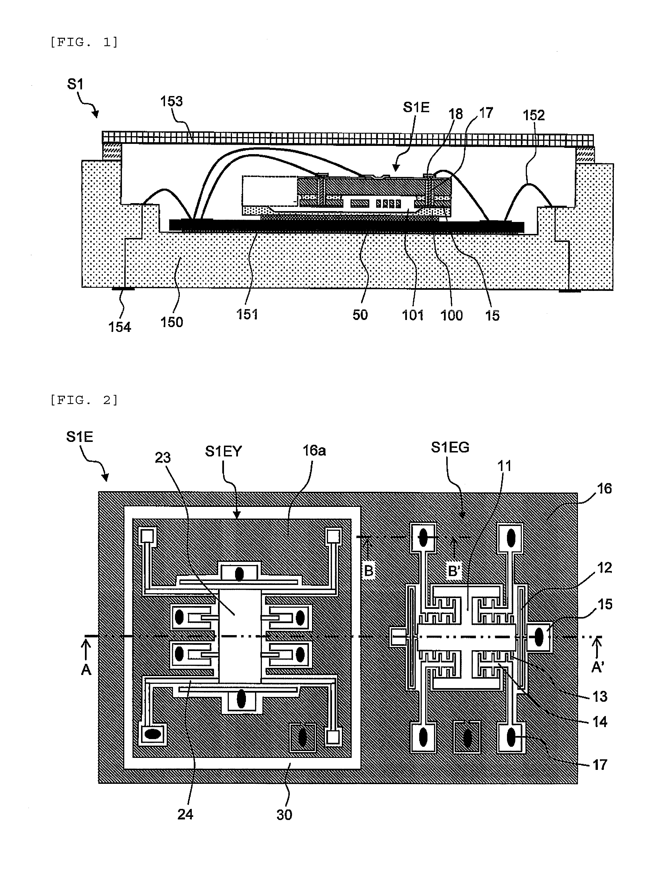
[0109]As described above, in the combined sensor S1 according to the first embodiment, a plurality of movable portions which detect an inertia are formed in the same layer and the dummy patterns arranged in the periphery of each movable portion are electrically separated from each other. Therefore, it is possible to apply the same potential to each movable portion and the peripheral dummy patterns and thus suppress a reduction in the S / N ratio, the offset, and a variation in sensitivity due to the potential difference between the peripheral dummy pattern and the movable portion.
[0110]In addition, the combined sensor S1 according to the first embodiment can adjust the reference potentials 20a and 20c to widen the adjustment range of a variation in the natural angular frequency due to a processing error during manufacturing. Therefore, it is possible to improve yield and reduce manufacturing costs.
second embodiment
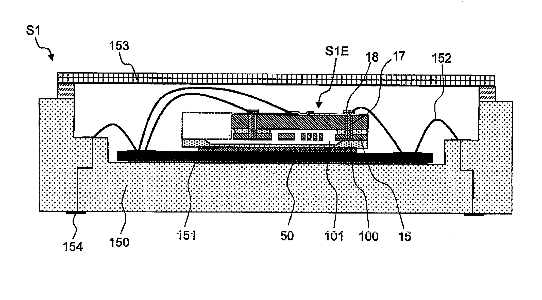
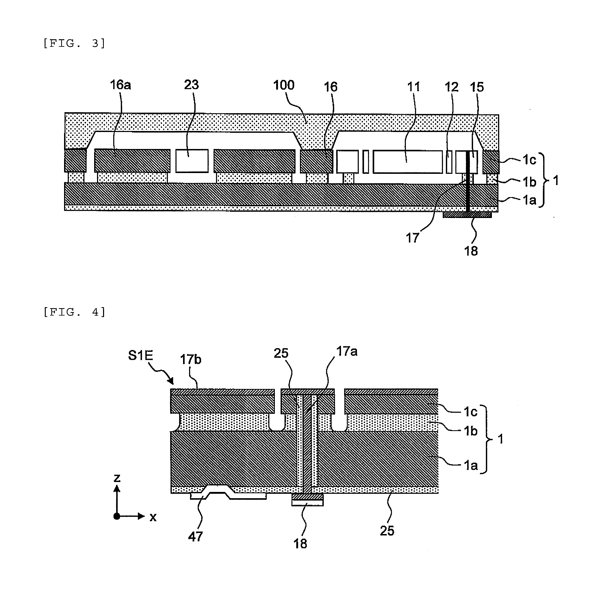
[0111]In the combined sensor S1 according to the first embodiment, the acceleration detecting unit S1EG and the angular velocity detecting unit S1EY are formed in the active layer 1c of the SOI substrate 1 and are fixed and suspended to the supporting layer 1a through the intermediate insulating layer 1b. Therefore, the inertial mass bodies 11 and 23 and the supporting layer 1a are electrically separated from each other and are mechanically arranged so as to face each other, with a gap corresponding to the thickness of the intermediate insulating layer 1b therebetween. That is, similarly to the dummy patterns 16 and 16a, it is necessary to fix potential in the supporting layer 1a.
[0112]Similarly to the structure in which the dummy pattern 16 of the acceleration detecting unit S1EG is electrically separated from the dummy pattern 16a of the angular velocity detecting unit S1EY and different potentials are applied to the dummy patterns 16 and 16a, a portion of the supporting layer 1a...
third embodiment
Summary
[0122]As described above, in the combined sensor S1 according to the third embodiment, the supporting layer 1a is not separated and the reference potential (20a or 20c) corresponding to one of the inertial mass bodies 11 and 23 which is more largely displaced by electrostatic force is applied. Therefore, it is possible to minimize the influence of the electrostatic force generated by the potential difference while solving the problems related to the strength of the combined sensor S1 or difficulty in processing.
Fourth Embodiment
[0123]In the first to third embodiments, the glass cap 100 including sodium and the SOI substrate 1 are bonded to each other by the anode bonding technique. However, a conductive substrate, such as a silicon substrate, may be bonded to the SOI substrate 1 by, for example, surface activated bonding, glass frit bonding, or a bonding technique using a metal adhesive. In this case, the cap 100 is arranged adjacent to, for example, the inertial mass body 11...
PUM
 Abstract
Description
Claims
Application Information
 - R&D
- Intellectual Property
- Life Sciences
- Materials
- Tech Scout
- Unparalleled Data Quality
- Higher Quality Content
- 60% Fewer Hallucinations
Browse by: Latest US Patents, China's latest patents, Technical Efficacy Thesaurus, Application Domain, Technology Topic, Popular Technical Reports.
© 2025 PatSnap. All rights reserved.Legal|Privacy policy|Modern Slavery Act Transparency Statement|Sitemap|About US| Contact US: help@patsnap.com