Monolithically integrated sic mosfet and schottky barrier diode

a technology of monolithic integrated sic mosfet and barrier diode, which is applied in the direction of diodes, semiconductor devices, electrical apparatus, etc., can solve the problems of poor efficiencies and limitations of switching frequency, inability to achieve cost reduction advantages, and difficulty in combining an sbd and a vertical mosfet. achieve the effect of reducing connections and bonding and increasing system reliability

Inactive Publication Date: 2013-11-28
MICROSEMI CORP ANALOG MIXED SIGNAL GRP LTD
View PDF4 Cites 43 Cited by
  • Summary
  • Abstract
  • Description
  • Claims
  • Application Information

AI Technical Summary

Benefits of technology

[0016]Increased system reliability due to reduced connections and bonding.

Problems solved by technology

This high Vf leads to poor efficiencies and limitations of switching frequency; furthermore the body diode may require an excessive cross-sectional area and therefore the cost reduction advantages are not realized.
Unfortunately, the combination of an SBD with a vertical MOSFET is not easily accomplished, particularly while enabling design freedom for the diode current carrying capability.
These two approaches have the straightforward limitation of process integration—different masks have to be designed to confine the process steps to the dedicated areas and the sequences of depositions and etches have to be carefully chosen to avoid the detrimental effect they might have on the main device (the Power MOSFET).
This has the same limitations as the previous efforts, i.e. the total area of the device has to be significantly larger to accommodate the SBD structure.
Also, in his patent, Cogan makes the incorrect assumption that the front side metals for the MOSFET and the SBD are the same, and this is not generally true, especially if a high quality, high Schottky barrier diode is to be paired with a Power MOSFET aimed for high temperature applications.

Method used


Image

  • Monolithically integrated sic mosfet and schottky barrier diode
  • Monolithically integrated sic mosfet and schottky barrier diode
  • Monolithically integrated sic mosfet and schottky barrier diode

Examples


Embodiment Construction

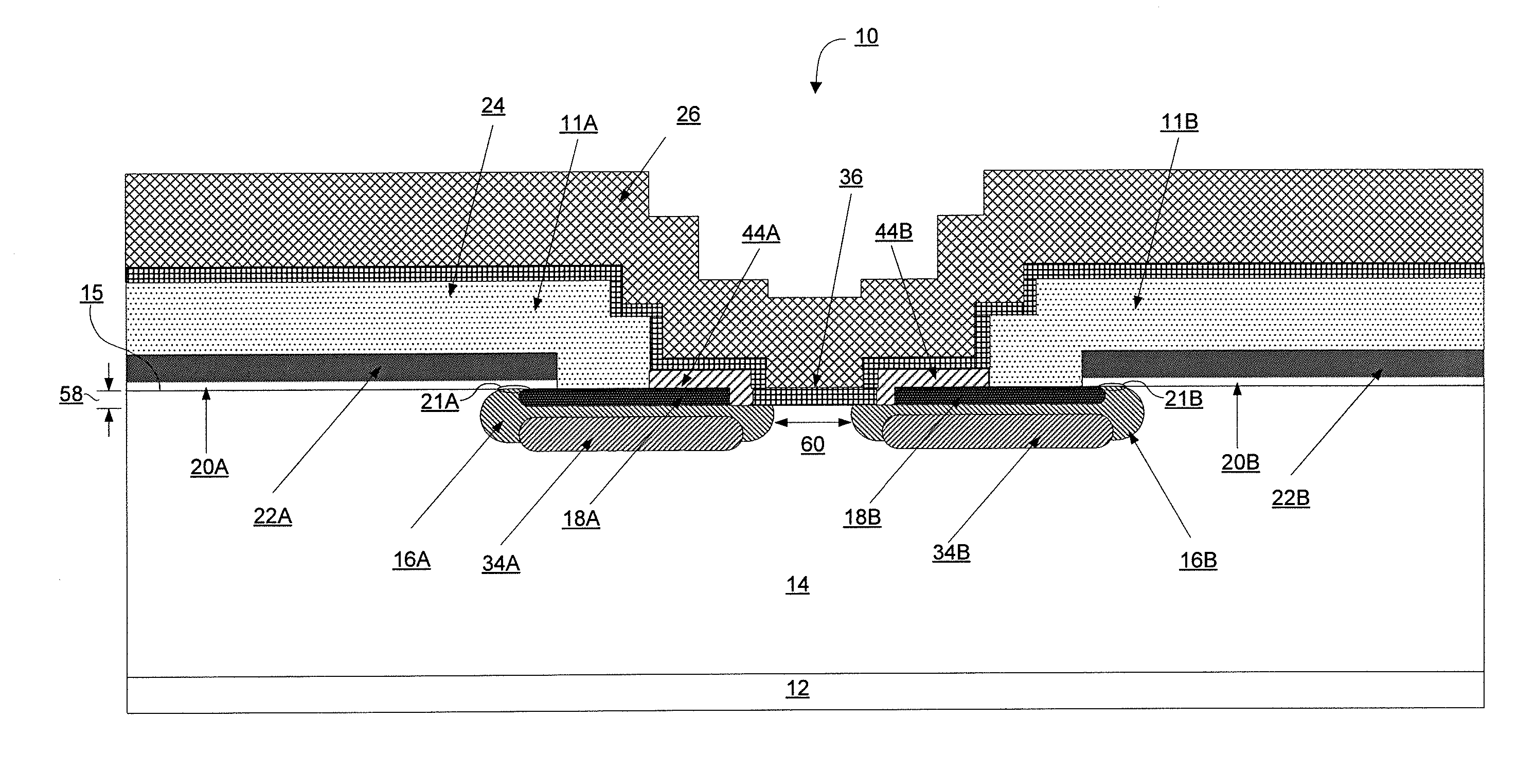
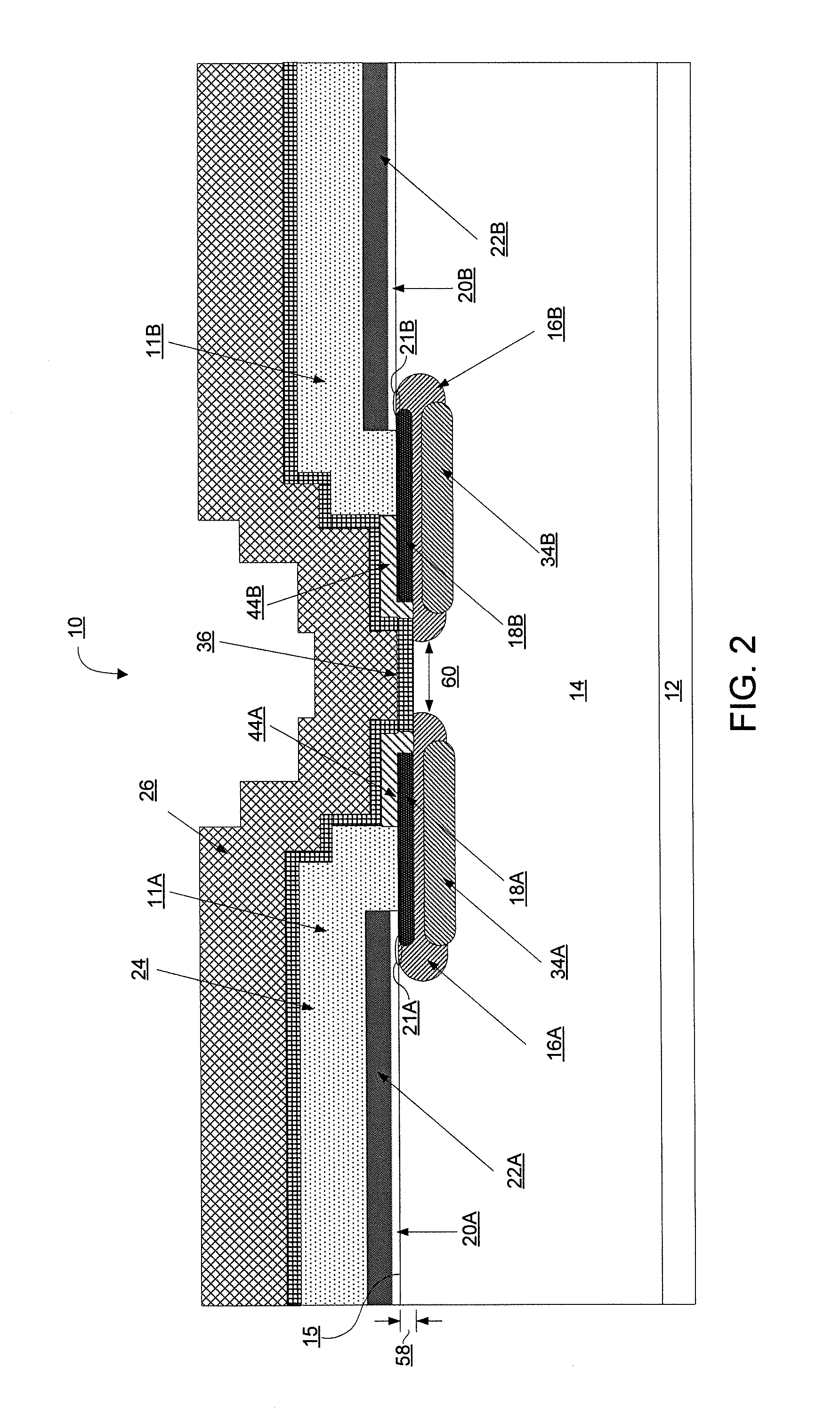
[0027]Before explaining at least one embodiment of the invention in detail, it is to be understood that the invention is not limited in its application to the details of construction and the arrangement of the components set forth in the following description or illustrated in the drawings. The invention is applicable to other embodiments or of being practiced or carried out in various ways. Also, it is to be understood that the phraseology and terminology employed herein is for the purpose of description and should not be regarded as limiting. Like structural features are given like reference numerals, to avoid redundant description.

[0028]The fabrication methods employed for silicon carbide devices must take into account that dopants have very low diffusivity and that implantation activation requires high anneal temperatures.

[0029]None of the teachings in the references discussed above sensed the benefits of trenching through the source and using a pull-back process to contact the ...


PUM


Abstract

A SIC VDMOS transistor is integrated with a SiC SBD, in a seamless way, without any increase of the device area. The SiC SBD is integrated in the active area of the VDMOS by splitting the P-Wells, such that the lightly doped drift region extents all the way to the surface of semiconductor, and by trenching through the source of the VDMOS and partially through the P-Wells to reach the peak of the P-type doping in the P-Well regions. The source of the VDMOS is contacted from the top surface and from the vertical sidewalls of the trenched source and the forward voltage of the Schottky Barrier diode is tailored by using two different metals for the ohmic contact on the source and for the SBD.

Description

CROSS REFERENCE TO RELATED APPLICATIONS[0001]This application claims the benefit of U.S. provisional patent application Ser. No. 61 / 651,090, filed May 24, 2012, herein incorporated by reference.BACKGROUND OF THE INVENTION[0002]This invention relates in general terms to vertical SiC Power MOSFETs and in particular to SiC Power MOSFETs where a SiC Schottky Barrier Diode (SBD) is integrated inside of the main structure of the Power MOSFET.[0003]Freewheeling diodes (FWD) are typical paired with switching transistors in power electronic circuitry. The FWD provides a path for current generated from the load when the switch is turned off, avoiding potential catastrophic reverse biasing of the switching transistor. FIG. 1 is an example schematic diagram of a typical implementation.[0004]It is advantageous to integrate the switch and FWD on the same semiconductor chip to reduce cost and improve circuit reliability. In the case of a silicon MOSFET switch, the body diode (a junction diode) may...

Claims


Application Information

Patent Timeline
Patent Type & Authority Applications(United States)
IPC IPC(8): H01L29/78H01L29/66
CPCH01L29/7806H01L29/66727H01L21/8213H01L27/0629H01L29/1608H01L29/66212H01L29/872
Inventor SDRULLA, DUMITRUVANDENBERG, MARC H.ODEKIRK, BRUCE
Owner MICROSEMI CORP ANALOG MIXED SIGNAL GRP LTD
Why Eureka
Try Eureka