
Semiconductor device and manufacturing method thereof

a semiconductor device and manufacturing method technology, applied in semiconductor devices, diodes, electrical devices, etc., can solve the problems of complex manufacturing process of semiconductor devices, and it is difficult to manufacture a semiconductor device at low cost, and achieve the effect of low cost and difficult manufacturing of semiconductor devices

Active Publication Date: 2013-11-28
ROHM CO LTD
View PDF1 Cites 23 Cited by
  • Summary
  • Abstract
  • Description
  • Claims
  • Application Information

AI Technical Summary

Benefits of technology

The present invention aims to provide a semiconductor device that is cost-effective and has reduced reverse leak current. The manufacturing process of the semiconductor device is simplified by forming a protective film on the entire surface of the n-type semiconductor layer before the trench for embedding the gate electrode is formed. The invention also reduces the reverse leak current in a reverse bias state.

Problems solved by technology

This makes the manufacturing process of the semiconductor device complex, and as a result, it becomes difficult to manufacture a semiconductor device at low cost.

Method used


Image

  • Semiconductor device and manufacturing method thereof
  • Semiconductor device and manufacturing method thereof
  • Semiconductor device and manufacturing method thereof

Examples


Embodiment Construction

[0064]Below, embodiments of the present invention will be explained in detail with reference to appended drawings.

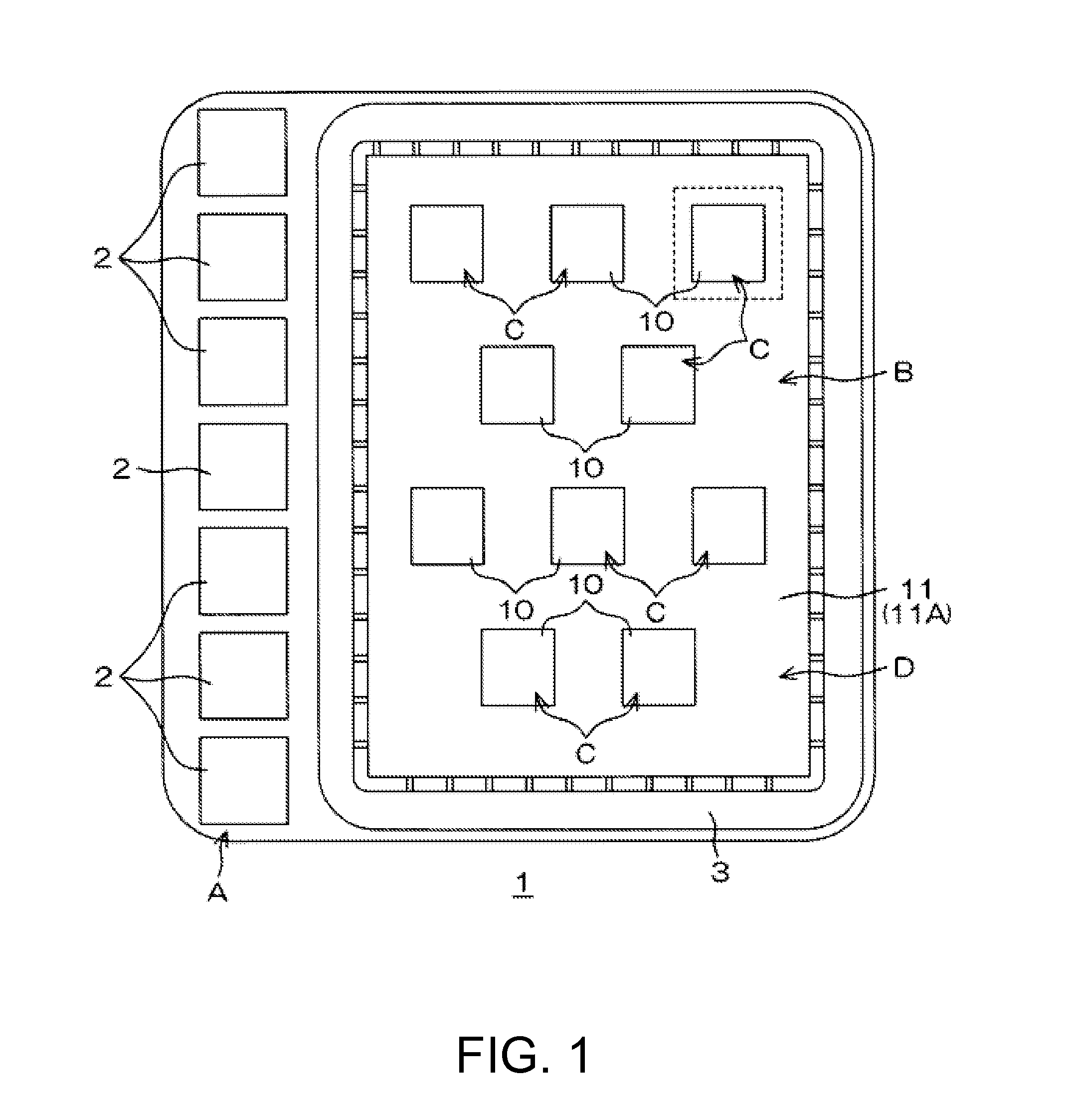
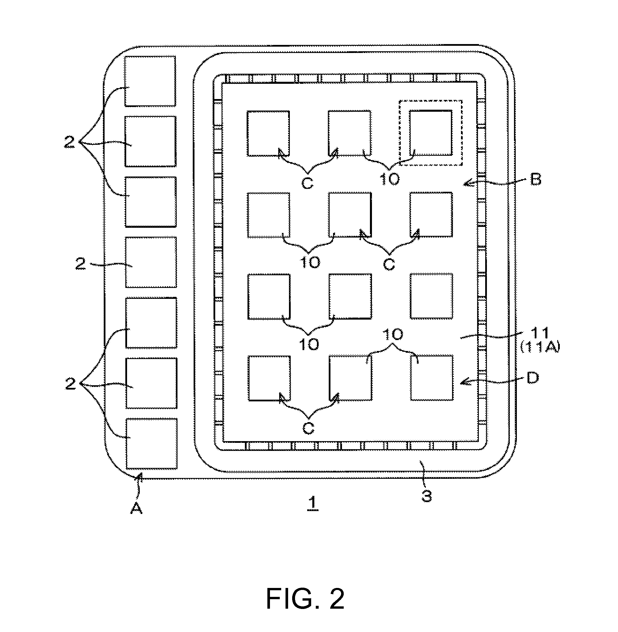
[0065]FIG. 1 is a schematic plan view of a semiconductor device of an embodiment of the present invention. FIG. 2 is a schematic plan view of a semiconductor device of another embodiment of the present invention.

[0066]A semiconductor device 1 of an embodiment of the present invention is formed to be a quadrangular chip in a plan view. The length of each of the four sides of the semiconductor device 1 in a plan view is approximately several mm, for example.

[0067]On the surface of the semiconductor device 1 having a quadrangular shape in a plan view, an external connection region A is formed along one side, and in a region other than the external connection region A, an active region B is formed. The semiconductor device 1 includes a plurality of external electrodes 2 disposed in the external connection region A, a guard ring 3 surrounding the active region B, a plurality ...


PUM


Abstract

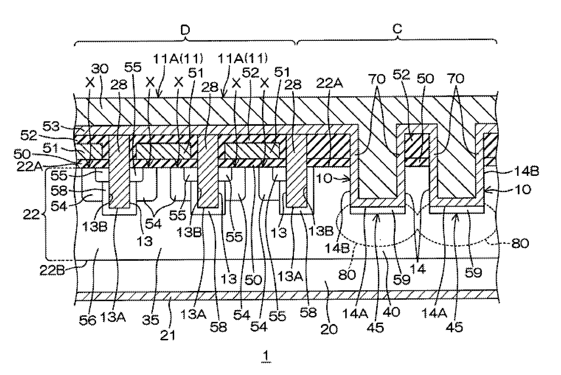
Provided is a semiconductor device that can be manufactured at low cost and that can reduce a reverse leak current, and a manufacturing method thereof. A semiconductor device has: a source region and a drain region having a body region therebetween; a source trench that reaches the body region, penetrating the source region; a body contact region formed at the bottom of the source trench; a source electrode embedded in the source trench; and a gate electrode that faces the body region. The semiconductor device also has: an n-type region for a diode; a diode trench formed reaching the n-type region for a diode; a p+ region for a diode that forms a pn junction with the n-type region for a diode at the bottom of the diode trench; and a schottky electrode that forms a schottky junction with the n-type region for a diode at side walls of the diode trench.

Description

[0001]This application claims the benefit of Japanese Application No. 2012-107673, filed in Japan on May 9, 2012, which is hereby incorporated by reference in its entirety.BACKGROUND OF THE INVENTION[0002]1. Field of the Invention[0003]The present invention relates to a semiconductor device and a manufacturing method thereof.[0004]2. Description of Related Art[0005]The semiconductor device disclosed in Patent Document 1 includes a schottky barrier diode connected between the source and the drain. More specifically, in the semiconductor device, a p-type base layer is formed in the surface portion of an n-type semiconductor layer formed on an n-type semiconductor substrate. A trench is formed from the surface of the n-type semiconductor layer so as to penetrate the p-type base layer, and on the side walls and the bottom of the trench, a gate insulating film is formed. A gate electrode is embedded in the trench. An n-type diffusion layer is formed in a surface portion of the p-type bas...

Claims


Application Information

Patent Timeline
IPC IPC(8): H01L21/8232H01L27/06
CPCH01L21/8232H01L27/06H01L27/0629H01L29/7806H01L29/7813H01L21/8234H01L29/4236H01L29/66143H01L29/66666
Inventor YOSHIMOCHI, KENICHI
Owner ROHM CO LTD
Learn More