

Switching Power Supply Device
- Summary
- Abstract
- Description
- Claims
- Application Information
AI Technical Summary
Benefits of technology
Problems solved by technology
Method used
Image

Examples
first embodiment
[0034][Overall Configuration]
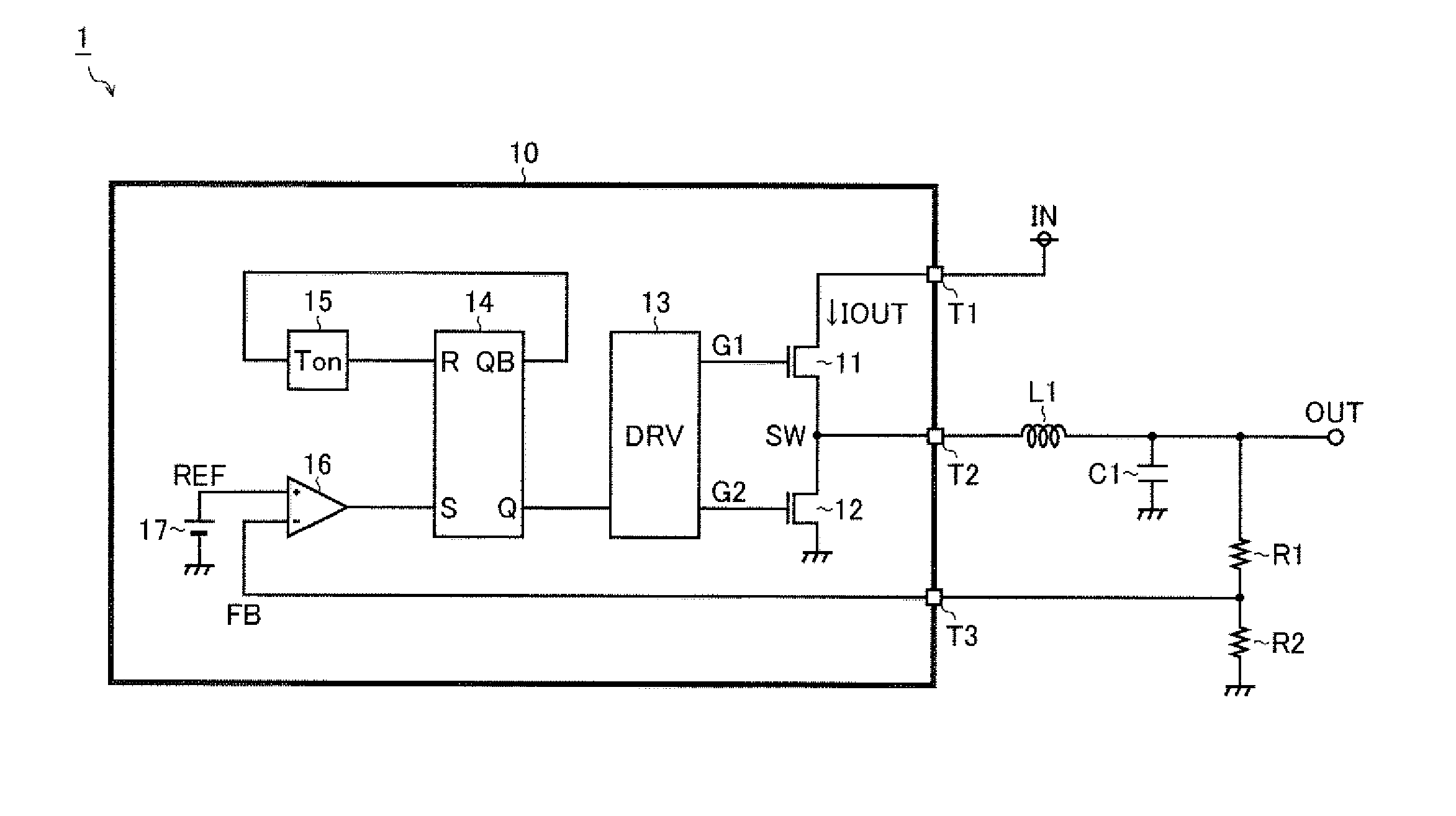
[0035]FIG. 1 is a block diagram showing a first embodiment of a switching power supply device. A switching power supply device 1 of the first embodiment is a voltage step-down DC / DC converter that generates an output voltage OUT from an input voltage IN by non-linear control (herein, fixed on-time with bottom detection control). The switching power supply device 1 has a semiconductor device 10 and various discrete components (an inductor L1, a capacitor C1, resistors R1 and R2) externally connected to the semiconductor device 10.
[0036]The semiconductor device 10 has at least external terminals T1 to T3 to establish an electrical connection with the outside. Outside the semiconductor device 10, the external terminal (power terminal) T1 is connected to an input end of the input voltage IN. The external terminal (switch terminal) T2 is connected to a first end of the inductor L1. A second end of the inductor L1, a first end of the capacitor C1, and a first ...
second embodiment
[0080][Overall Configuration]
[0081]FIG. 6 is a block diagram showing a second embodiment of the switching power supply device. A switching power supply device 1 of the second embodiment is characterized by a configuration based on the foregoing first embodiment, to which a ripple injection unit 18 and a backflow current detection unit 19 are added.
[0082]The ripple injection unit 18 injects into a reference voltage REF a ripple component generated by using a gate signal G1 and a switch voltage SW, and outputs to a non-inverted input terminal (+) of a comparator 16 a reference voltage REF2 obtained by the ripple injection. With this ripple injection technique introduced, even when a ripple component of an output voltage OUT (accordingly, of a feedback voltage FB) is not so large, stable switching control can be performed, and thus it is made possible to use, as a capacitor C1, for example, a laminated ceramic capacitor having a small ESR (equivalent series resistance).
[0083]The backfl...
modification examples
OTHER MODIFICATION EXAMPLES
[0138]While the descriptions of the foregoing embodiments exemplarily use a configuration in which the present invention is applied to a synchronous rectification type voltage step-down switching power supply device, there is no limitation thereto, and the present invention may be applied to a case where switching is driven by non-synchronous rectification and to a case where the switching power supply device has a voltage step-up or voltage step-up / -down type output stage.
[0139]As discussed above, the present invention is not limited in configuration to the foregoing embodiments, and various modifications can be made thereto within the spirit of the invention. That is, the foregoing embodiments are to be construed in all respects as illustrative and not limiting. It is to be understood that the technical scope of the present invention is indicated by the appended claims rather than by the above descriptions of the embodiments, and all changes that come wi...
PUM
 Abstract
Description
Claims
Application Information