Catalytic converter

a converter and catalytic technology, applied in the direction of machines/engines, lighting and heating apparatus, separation processes, etc., can solve the problems of increasing pressure loss with respect to the flow of exhaust gas, reducing the amount of exhaust gas that flows in, and releasing toxic substances to the environment, so as to increase the warm-up capability, reduce the amount of exhaust gas that flows in, and reduce the effect of pressure loss

Inactive Publication Date: 2013-11-28
TOYOTA JIDOSHA KK +1
View PDF5 Cites 3 Cited by
  • Summary
  • Abstract
  • Description
  • Claims
  • Application Information

AI Technical Summary

Benefits of technology

[0016]The catalytic converter of the aspect of the invention described above includes the first carrier and the second carrier that each have a cell structure, in order from upstream in the exhaust gas flow direction. Also, in the catalytic converter of the aspect of the invention described above, the first carrier and the second carrier have cell densities opposite those of the catalytic converter shown in FIG. 7. That is, in the first carrier that is positioned upstream, the cell density of the first peripheral region is higher than the cell density of the first center region, and in the second carrier that is positioned downstream, the cell density of the second center region is higher than the cell density of the second peripheral region. In this structure, exhaust gas that has flowed into the catalytic converter first flows into the upstream first carrier. The cell density of the first center region of the upstream first carrier is lower than that of the first peripheral region, so pressure loss with respect to the exhaust gas flow is relatively low. Therefore, the exhaust gas flows easily through the first center region of the first carrier, so the amount of exhaust gas that flows in increases. This increase in the amount of the exhaust gas that flows in promotes the supply of heat to the catalytic converter, so the warm-up capability immediately after engine startup increases. As a result, with this increase in warm-up capability immediately after engine startup, the emission (cold emission) of HC and NOx and the like is effectively suppressed.
[0017]Also, the exhaust gas that has passed through the first center region of the first carrier flows mainly through the second peripheral region where the cell density and pressure loss are low, in the second carrier that is positioned downstream. In this way, in the second carrier that is positioned downstream, the exhaust gas flow is promoted in the second peripheral region. As a result, the exhaust gas flow distribution that is larger at the first center region of the upstream first carrier is distributed to the second peripheral region in the downstream second carrier. Therefore, when the carrier is viewed as a whole, the exhaust gas flow distribution is rectified to a flow distribution that is as uniform as possible. This kind of exhaust gas flow distribution rectifying action by the second carrier enables the precious metal catalyst of the entire carrier to be effectively utilized, such that a catalytic converter having high exhaust gas purifying performance is able to be obtained.
[0018]According to the catalytic converter of this aspect of the invention, the amount of exhaust gas that flows therein increases, so the supply of heat to the catalytic converter is promoted. Therefore, the cold emission reduction effect is increased with the improvement in the warm-up capability immediately after engine startup. Furthermore, the exhaust gas flow distribution that increases at the center region of the upstream first carrier is distributed to the peripheral region in the downstream second carrier, so the exhaust gas flow distribution is rectified to as uniform a flow distribution as possible. Accordingly, the precious metal catalyst of the entire carrier is effectively utilized, so the exhaust gas purifying performance improves.

Problems solved by technology

The engine may discharge toxic substances to the environment, such as CO, NOx, unburned HC, and volatile organic compounds (VOC) and the like.
However, if the cell density of the center region of the upstream catalyst into which the exhaust gas that has entered the catalytic converter first flows is large, as is shown in FIG. 7, pressure loss with respect to the exhaust gas flow will increase.
As a result, with the catalytic converter shown in FIG. 7, the exhaust gas will not flow as easily, so the amount of exhaust gas that flows in may end up decreasing.
If the amount of exhaust gas that flows into the catalytic converter decreases in this way, the supply of heat to the catalytic converter will also naturally decrease, and the warm-up capability immediately after engine startup will decrease.

Method used


Image

  • Catalytic converter
  • Catalytic converter
  • Catalytic converter

Examples


Embodiment Construction

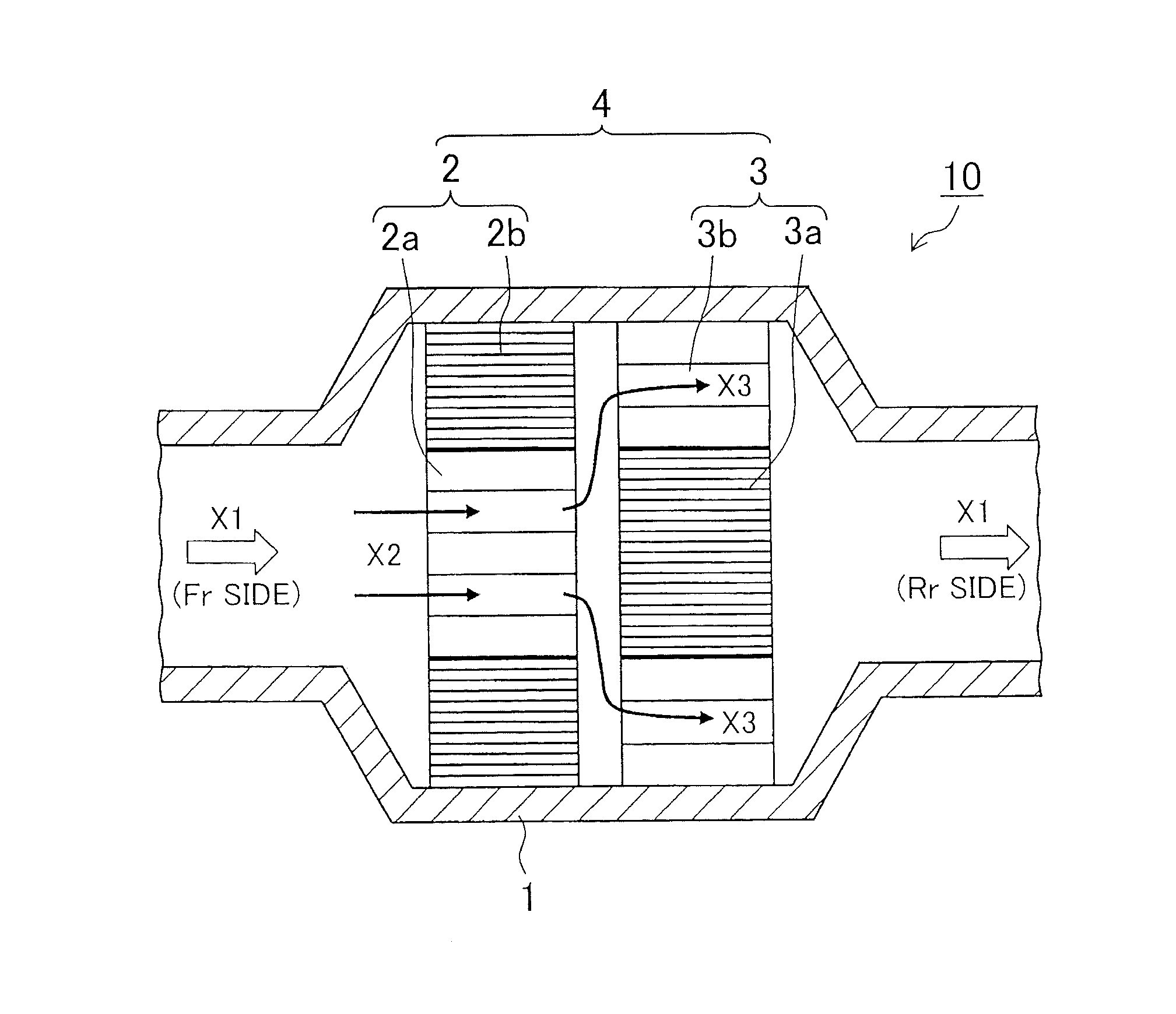
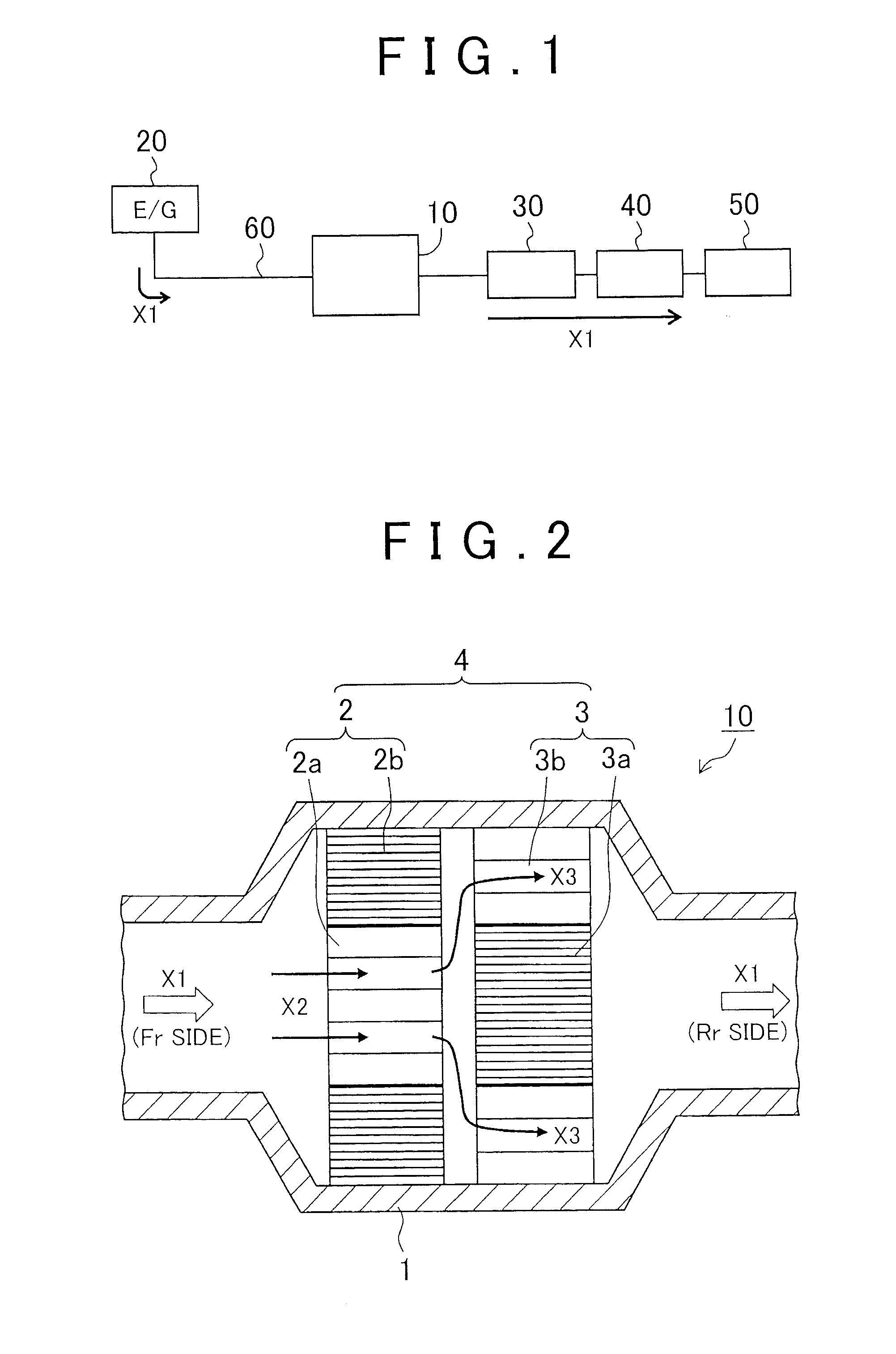
[0027]Hereinafter, example embodiments of a catalytic converter of the invention will be described with reference to the accompanying drawings. FIG. 1 is a view showing a frame format of an exhaust system for exhaust gas, in which a catalytic converter according to one example embodiment of the invention is interposed.

[0028]The exhaust system for exhaust gas includes an engine 20, a catalytic converter 10, a three-way catalytic converter 30, sub muffler 40, and a main muffler 50. The engine 20 and the catalytic converter 10 are connected by a system conduit 60. Similarly, the catalytic converter 10 is connected to the three-way catalytic converter 30, the three-way catalytic converter 30 is connected to the sub muffler 40, and the sub muffler 40 is connected to the main muffler 50, all via the system conduit 60. That is, the engine 20 is connected to an upstream portion of the catalytic converter 10 via the system conduit 60. Exhaust gas produced by the engine 20 is discharged in di...


PUM

PropertyMeasurementUnit
lengthaaaaaaaaaa
diameteraaaaaaaaaa
cell densityaaaaaaaaaa

Abstract

A catalytic converter has a carrier with a cell structure, and a precious metal catalyst carried on the carrier. The carrier includes a first carrier and a second carrier. The second carrier is provided downstream of the first carrier in a gas flow direction of gas that flows into the catalytic converter. The first carrier has a first peripheral region and a first center region that has a lower cell density than the first peripheral region. The second carrier has a second center region and a second peripheral region that has a lower cell density than the second center region.

Description

[0001]The disclosure of Japanese Patent Application No. 2012-118519 filed on May 24, 2012 including the specification, drawings and abstract is incorporated herein by reference in its entirety.BACKGROUND OF THE INVENTION[0002]1. Field of the Invention[0003]The invention relates to a catalytic converter provided in a conduit that forms an exhaust system for exhaust gas.[0004]2. Description of Related Art[0005]In various industrial fields, various efforts to reduce environment impact are being made on a global scale. Of these, in the automotive industry, in addition to a development of gasoline engine vehicles with sufficient fuel efficiency performance, so-called eco-cars (ecologically-friendly cars) such as hybrid vehicles and electric vehicles are being popularized, and developments are being made to further improve the performance of these vehicles.[0006]Typically, a catalytic converter for purifying exhaust gas is arranged in an exhaust system for exhaust gas that connects a vehi...

Claims


Application Information

Patent Timeline
Patent Type & Authority Applications(United States)
IPC IPC(8): B01D53/94
CPCB01D53/94B01D2255/9202B01D2255/904B01D53/9477
Inventor SUZUKI, HIROMASANAKANO, MICHIHARUKAKINOHANA, MASARUMATSUBARA, HIROYUKIMURATA, MASAKAZUHAYASHI, NAOHIRO
Owner TOYOTA JIDOSHA KK
Why Eureka
Try Eureka