
Resin composition for light scattering layer, light scattering layer,and organic electroluminescence device

Inactive Publication Date: 2013-12-12
TOYO INK SC HOLD CO LTD +1
View PDF3 Cites 21 Cited by
  • Summary
  • Abstract
  • Description
  • Claims
  • Application Information

AI Technical Summary

Benefits of technology

The present invention provides a resin composition for a light scattering layer that can improve the light extraction efficiency of an organic EL device, with a small wavelength dependence and can be used in a wide wavelength range. Additionally, the resin composition can form a light scattering layer that can achieve a high light extraction efficiency without inducing fine cracking, protrusion, or peeling in the translucent electrode during production of a laminated structure. The technical effects include improving the light extraction efficiency of the organic EL device and achieving a high-efficient device without inducing fine cracking, protrusion, or peeling in the translucent electrode.

Problems solved by technology

For this reason, total reflection or interference is liable to occur at an interface of emitted light, and the light extraction efficiency is less than 20%, and thus most light is lost.
Then, the light is absorbed inside the element and attenuates, which makes it difficult to extract the light to the outside.
Accordingly, the above-mentioned methods disclosed in Japanese Unexamined Patent Application Publication Nos. 2004-296429, 2005-190931, and 2009-110930 have a problem that the color tone varies when the methods are used in a wide wavelength range.
However, this method has a problem that the luminance varies in each color pixel, which results in impairing the white balance.
However, this method requires complicated processes, and thus is impractical.
In this case, when the adhesive property between the base material and the translucent electrode is low, fine cracking or peeling occurs in the translucent electrode.
As a result, when the organic EL device is caused to emit light, a dark spot, luminance unevenness, or shortening of lifetime is caused.
As a result, a short circuit or shortening of lifetime may be caused.
When a material obtained by forming a light scattering layer of related art on a translucent substrate is used as the base material, the adhesive property between the base material and the translucent electrode and the evenness of the base material are not sufficient, which may cause the above-mentioned problems.

Method used

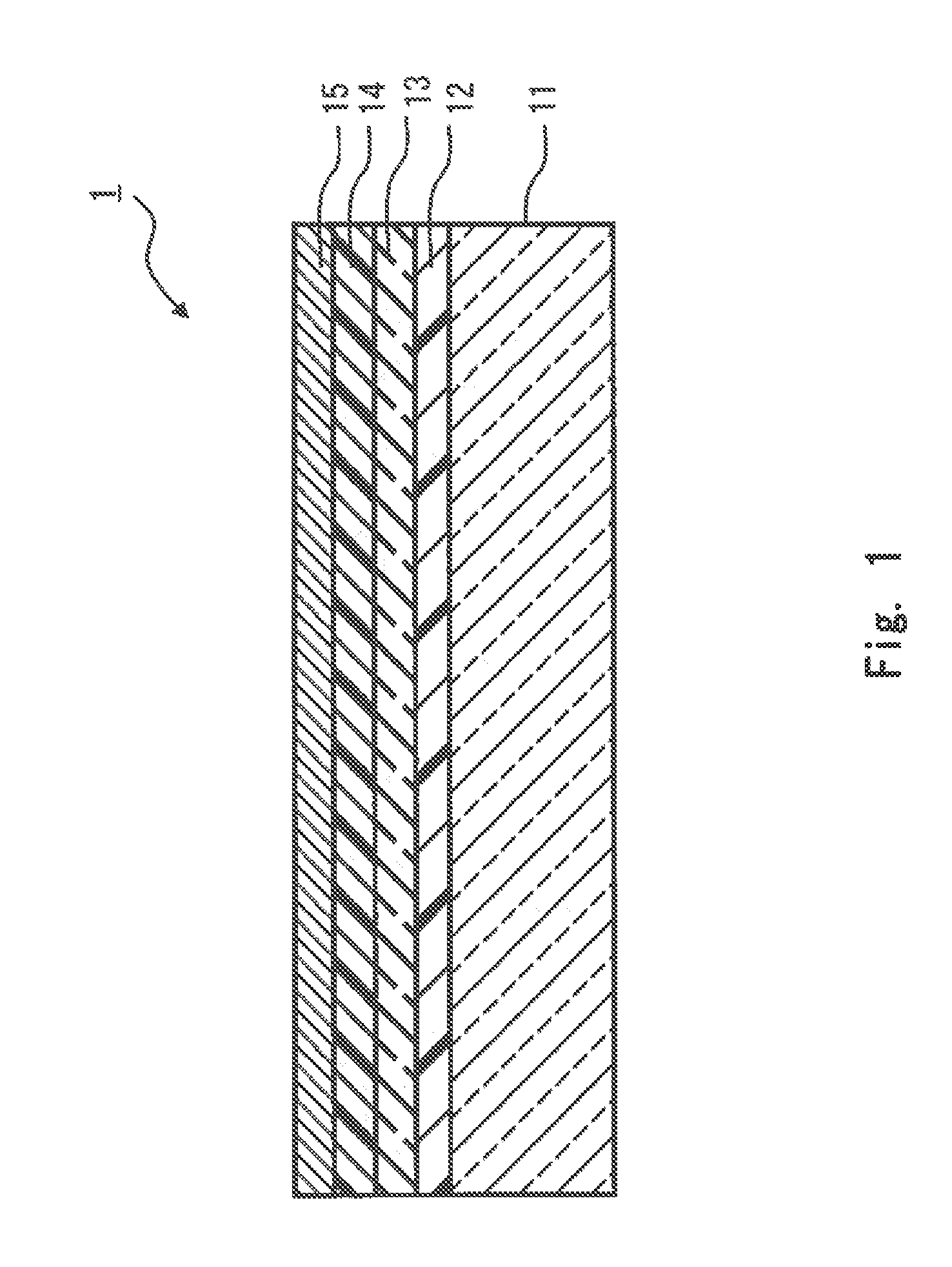
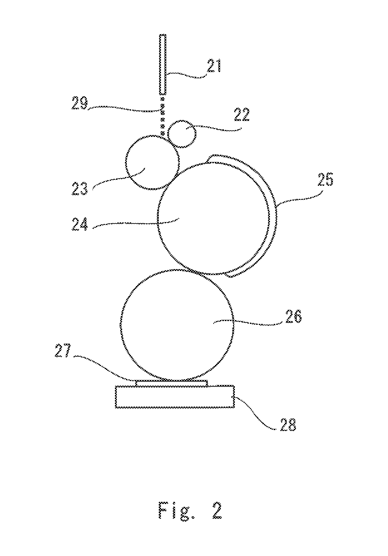

Image

  • Resin composition for light scattering layer, light scattering layer,and organic electroluminescence device
  • Resin composition for light scattering layer, light scattering layer,and organic electroluminescence device
  • Resin composition for light scattering layer, light scattering layer,and organic electroluminescence device

Examples


production example 1-1

Process 1:

[0345]In a reaction container including a stirrer, a thermometer, a dropping device, a reflux cooler, and a gas introducing tube, 100 parts of PGMEA (propyleneglycol monomethyl ether acetate) were introduced as a solvent. A nitrogen gas was injected into this container and heated to 80° C. This temperature was held, and a mixture of 5.0 parts of styrene (St), 15.9 parts of cyclohexyl methacrylate (CHMA), 31.7 parts of methacrylic acid (MAA), and 3.0 parts of 2,2′-azobisisobutyronitrile was dropped for one hour and was subjected to polymerization reaction. After completion of dropping, the mixture was further subjected to reaction for three hours at 70° C. After that, a solution obtained by dissolving 0.5 parts of azobisisobutyronitrile into 40 parts of PGMEA was added and continuously stirred at the same temperature for three hours, so that a copolymer was obtained.

Process 2:

[0346]Next, dry air was introduced into the reaction container, and 50.0 parts of glycidyl methacry...

production example 1-11

[0351]Process 1: Production of a dispersant (T1-1)

[0352]In a 4-necked flask including a stirrer, a reflux condenser tube, a dry air inlet tube, and a thermometer, 80.0 parts of biphenyl tetracarboxylic acid dianhydride (manufactured by Mitsubishi Chemical Corporation), 250.0 parts of pentaerythritol triacrylate (manufactured by NIPPON KAYAKU Co., Ltd., Product Name: KAYARAD PET-30), 0.16 parts of hydroquinone (manufactured by Wako Pure Chemical Industries, Ltd.), and 141.2 parts of cyclohexanone were fed and heated to 85° C. Next, 1.65 parts of 1,8-diazabicyclo[5.4.0]-7-undecene (manufactured by Tokyo Chemical Industry Co., Ltd.) were added as a catalyst and stirred for eight hours at 85° C. After that, 77.3 parts of glycidyl methacrylate (manufactured by Dow Chemical Japan Ltd.) and 33.9 parts of cyclohexanone were added, and then, 2.65 parts of dimethylbenzylamine (manufactured by Wako Pure Chemical Industries, Ltd.) were added as a catalyst, were stirred for six hours at 85° C., ...

production example 1-12

[0356]Under an N2 atmosphere, in a mixed solvent of 58 g of methanol and 32 g of water, 4.5 g of methyl methacrylate (manufactured by Wako Pure Chemical Industries, Ltd.), 5 g of trifluoroethyl methacrylate (manufactured by Wako Pure Chemical Industries, Ltd.), and 0.5 g of allyl methacrylate (manufactured by Wako Pure Chemical Industries, Ltd.) were polymerized for eight hours at 60° C. by use of 0.025 g of 2,2′-azobis(2-amidinopropane)dihydrochloride (manufactured by Wako Pure Chemical Industries, Ltd., V-50). After that, 123 g of PGMEA 123 g were added, and methanol and water were removed by stripping. Thus, a light scattering particle dispersion liquid (B1-2) (acrylic resin particle dispersion liquid) was prepared.

[0357]Table 2 shows the composition of the light scattering particle dispersion liquid (B1-2), the dispersion device, the primary particle diameter of particles, the diameter of particles in the dispersion liquid, the content of particles having a particle diameter of ...


PUM

PropertyMeasurementUnit
Fractionaaaaaaaaaa
Percent by massaaaaaaaaaa

Abstract

Provided is a resin composition for light scattering layer for use in forming a light scattering layer of an organic EL device, including: a binder composition including at least one type of resin (A); and light scattering particles (B). In a resin composition for light scattering layer of the invention, the light scattering particles (B) have an average particle diameter of 200 nm to 500 nm in the resin composition and have a content of 20 vol % or less of particles with a particle diameter of 600 nm or more with respect to a total amount of the light scattering particles (B); and a refractive index difference between the binder composition and the light scattering particles (B) is 0.1 or more.

Description

INCORPORATION BY REFERENCE[0001]This application is based upon and claims the benefit of priority from Japanese patent application No. 2012-132439, filed on Jun. 12, 2012, the disclosure of which is incorporated herein in its entirety by reference.BACKGROUND OF THE INVENTION[0002]1. Field of the Invention[0003]The present invention relates to a resin composition for light scattering layer, which is used to improve the luminous efficiency of an organic electroluminescence (hereinafter referred to also as “EL”) device, a light scattering layer formed of the resin composition for light scattering layer, and an organic EL device including the light scattering layer.[0004]2. Description of Related Art[0005]An organic EL device is a spontaneous light emitting element which utilizes the principle that a fluorescent substance or the like emits light by energy of recombination of holes injected from an anode and electrons injected from a cathode when an electric field is applied. In recent y...

Claims


Application Information

Patent Timeline
IPC IPC(8): C08K3/22C08L33/00C08K5/103H01L51/50H05B33/02
CPCC08K3/22C08K5/103C08L33/00C08L23/0815C08L23/0876G02B5/0242G02B5/0268G02B5/0278C08K5/5455H10K50/854
Inventor KIDA, KANAIWATA, TOHRUCHISAKA, JIROHIRANO, AKIRAKONDO, KEIICHI
Owner TOYO INK SC HOLD CO LTD
Learn More