Electro-medical system for neuro-muscular paralysis assessment

a neuromuscular and electromedical system technology, applied in the field of electromedical device system improvement, can solve the problems of inability to inability to accurately predict the effect of nmb antidote administration,

Active Publication Date: 2013-12-12
ONDINE TECH
View PDF9 Cites 21 Cited by
  • Summary
  • Abstract
  • Description
  • Claims
  • Application Information

AI Technical Summary

Benefits of technology

[0013]In yet another aspect, the inventive concept pertains to a non-transitory computer-readable medium storing instructions that, when executed, causes a computer to perform a method for quantitatively determining a person's neuro-muscular blockade (NMB) level in real-time using at least one sensor attached to the person. The method includes receiving a first input signal from the sensor, wherein the first input signal includes a measurement of a first muscular response, the first muscular response resulting from a baseline stimulus cur

Problems solved by technology

More specifically, an excessive dose as well as a low dose of antidote can be dangerous and life threatening.
Administering excessive NMB antidote runs the risk of recurarization in some patients.
Recurarization is subjective to a patient and his condition; it is not predictable, nor easily reproducible.
Failure to recognize and promptly treat recurarization often leads to death.
However, clinical criteria are subjective, causing doubt about clinical residual NMB.
A problem with current patient monitoring systems is the lack of a quantitative measure of the degree of patient neuro-muscular blockade (paralysis).
Yet, there is no device that helps the anesthesiologist accurately determine the end point of the paralysis.
A patient's muscle has a unique neuromuscular threshold to electrical stimulation that is further modulated by electrode placement and quality of electrode's electrical contact with the skin, and currently available devices are unable to factor in these neuromuscular thresholds.
Some devices do not keep a record

Method used


Image

  • Electro-medical system for neuro-muscular paralysis assessment
  • Electro-medical system for neuro-muscular paralysis assessment
  • Electro-medical system for neuro-muscular paralysis assessment

Examples


Embodiment Construction

[0043]The following description is of the best mode presently contemplated for carrying out the invention. It is not to be taken in limiting sense, but is made merely for the purpose of describing the general principles of the invention.

[0044]Reference will now be made in detail to the exemplary embodiments illustrated in the accompanying drawings. Wherever possible, the same reference numbers will be used throughout the drawings to refer to the same or like parts.

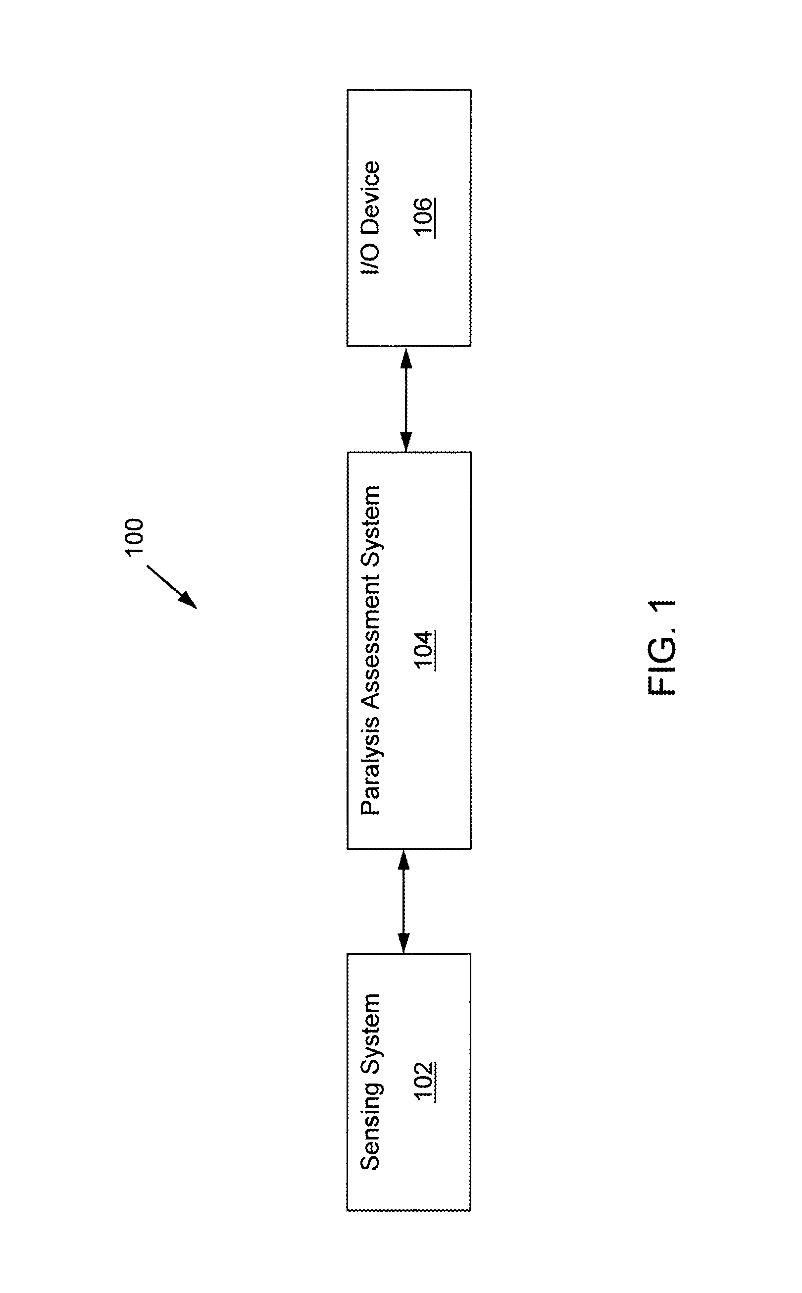
[0045]FIG. 1 illustrates a block diagram of an exemplary system 100 consistent with the invention. As shown in FIG. 1, exemplary system 100 may include a sensing system 102, a paralysis assessment system 104, and an input / output (I / O) device 106. Each of the components is operatively connected to one another via a network or any type of communication links that allow transmission of data from one component to another. The network may include Local Area Networks (LANs) and / or Wide Area Networks (WANs), and may be wireless, ...


PUM


Abstract

A computer-implemented method for quantitatively determining a person's neuro-muscular blockade (NMB) level in real-time using at least one sensor attached to the person is provided. The method includes receiving a first input signal from the sensor, wherein the first input signal includes a measurement of a first muscular response, the first muscular response resulting from a baseline stimulus current delivered to the person before administration of NMB agents to the person, and establishing a baseline chronaxie based on the first input signal. The method also includes delivering one or more stimulus currents to the person after the administration of NMB agents to the person, receiving a second input signal from the sensor, wherein the second input signal includes a measurement of one or more muscular responses resulting from the one or more stimulus currents, and determining the person's NMB level based on the second input signal.

Description

CROSS REFERENCE TO RELATED APPLICATIONS[0001]The present application claims the benefit of U.S. Provisional Patent Application No. 61 / 657,779 entitled “ELECTRO-MEDICAL SYSTEM FOR NEURO-MUSCULAR PARALYSIS ASSESSMENT,” which was filed on Jun. 9, 2012.FIELD OF INVENTION[0002]The present invention relates to an improved electro-medical device system, suitable for determining the extent of neuro-muscular blockade (NMB) during hospital operation room administration of general anesthesia, other medical procedures and medical attention to in face of neurotoxin based chemical accidents. The device uses the physiological concept of Chronaxie to determine the patient's level of neuro-muscular blockade in digital and quantitative format under an anesthesia agent. The device is suitable to operate in an electrical energy budget constraint, and more particularly, to a very low-powered, wirelesses or wired, non-invasive patient monitoring system.[0003]In the existing state of the art (e.g., curren...

Claims


Application Information

Patent Timeline
IPC IPC(8): A61B5/11A61B5/0205
CPCA61B5/1106A61B5/0205A61B2505/05A61B2562/0219
Inventor MATHUR, AMITABH MOHANMATHUR, RADHEY MOHANSHARMA, ARUN KUMARDURVASULA, VENKATA MURTHY
Owner ONDINE TECH
Why Eureka
Try Eureka