Electric tool and method of driving electric tool

a technology of electric tools and electric motors, applied in the field of electric tools, can solve the problems of reduced increased circuit consumption, and accelerated consumption of secondary batteries, and achieve the effect of reducing the work rate per one charging operation and increasing circuit consumption

Inactive Publication Date: 2013-12-19
HITACHI KOKI CO LTD
View PDF0 Cites 17 Cited by
  • Summary
  • Abstract
  • Description
  • Claims
  • Application Information

AI Technical Summary

Benefits of technology

[0003]In order to boost the battery of the secondary battery to charge the capacitor, various circuits are required to control the current, and a current consumption of

Problems solved by technology

In order to boost the battery of the secondary battery to charge the capacitor, various circuits are required to control the current, and a current consumption of the circuits increases.
This leads to such a problem that the consumption of the secondary battery is accelerated, and a work rate per one charging operation is reduced.

Method used


Image

  • Electric tool and method of driving electric tool
  • Electric tool and method of driving electric tool
  • Electric tool and method of driving electric tool

Examples


Embodiment Construction

[0135]Hereinafter, a preferred embodiment of the present invention will be described in detail with reference to the drawings. The same or equivalent constituent elements, members, and processing illustrated in the respective drawings are denoted by identical symbols, and a repetitive description will be appropriately omitted. The embodiment does not limit the present invention, but exemplify the present invention, and all of the features described in the embodiment, and a combination thereof are not always essential to the present invention.

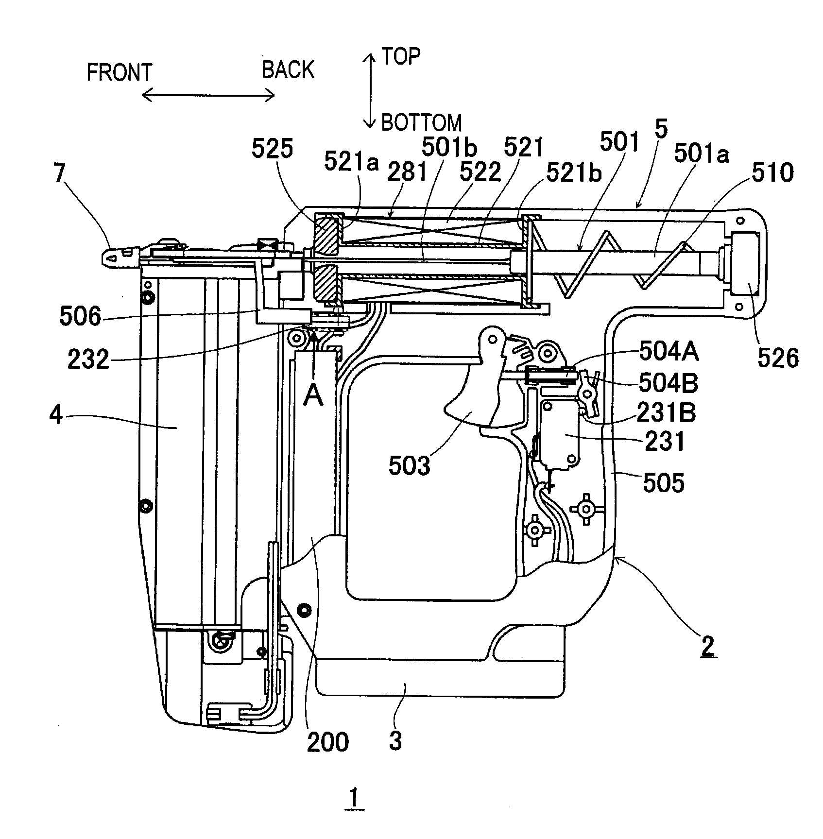
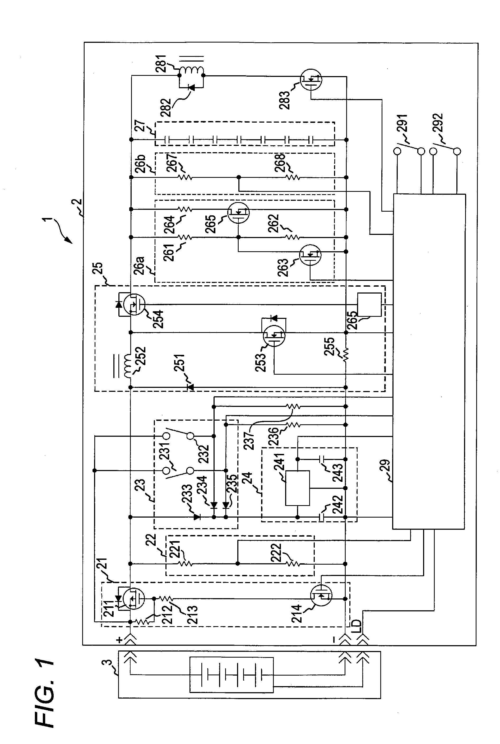
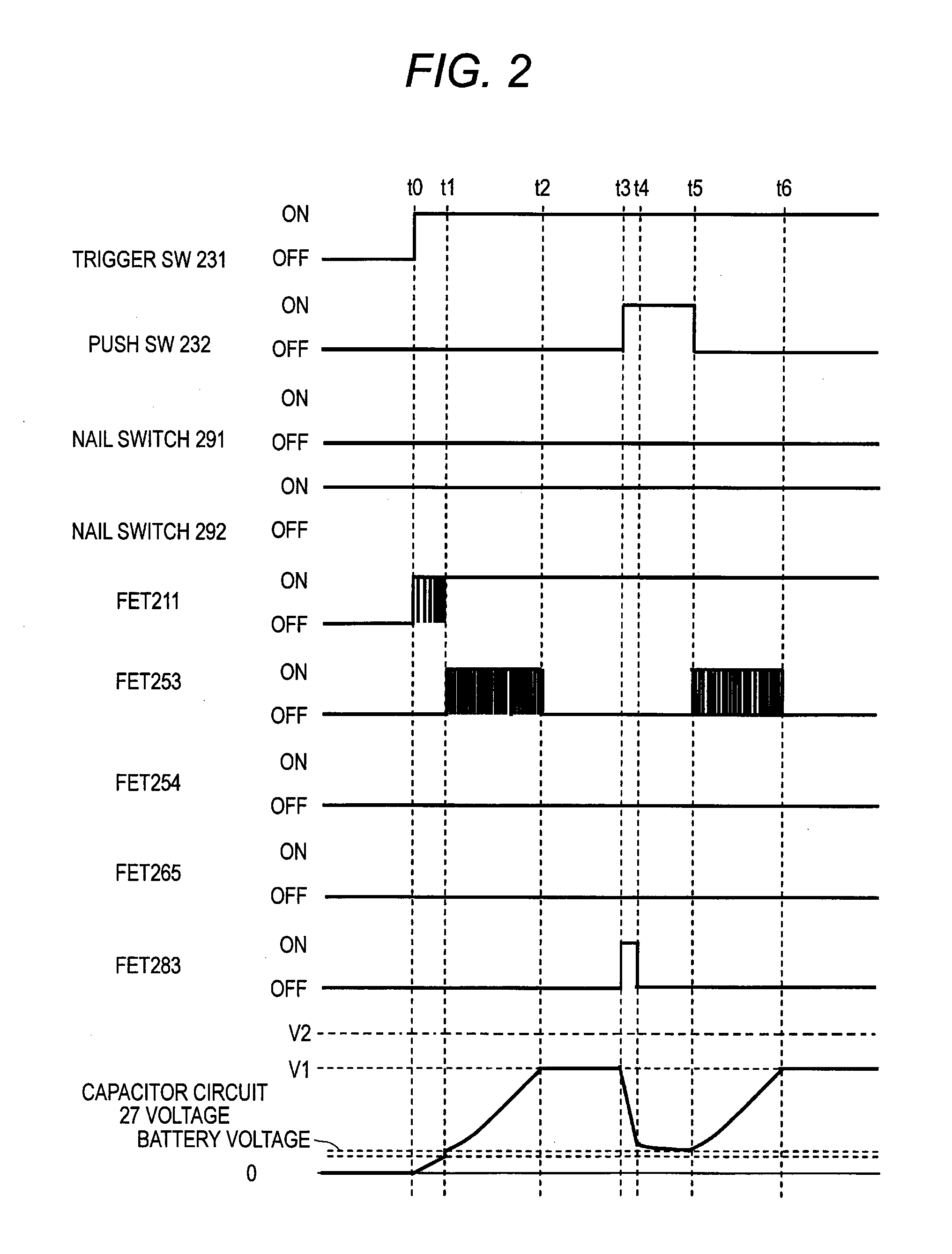
[0136]FIG. 1 is a circuit diagram of an electric tool 1 according to an embodiment of the present invention. FIGS. 2 to 4 are timing charts illustrating temporal changes in on / off operation of respective switches in the circuit illustrated in FIG. 1 and a voltage across a capacitor circuit 27. FIG. 5 is a flowchart illustrating the operation of the circuit illustrated in FIG. 1. FIG. 6 is an external view of the electric tool 1. FIG. 7A is a par...


PUM


Abstract

When a work stops without driving after a voltage across a capacitor circuit reaches a target boost voltage, a micro-computer switches an FET through a driver circuit. As a result, the voltage charged in the capacitor circuit is charged in a secondary battery through the FET, an inductance, and a parasitic diode of an FET.

Description

TECHNICAL FIELD[0001]The present invention relates to an electric tool driven by a secondary battery and a method of driving an electric tool, which are suitable for driving the fastener such as a nail or a staple into a material such as wood.BACKGROUND ART[0002]A cordless tool having a motor driven by a charged secondary battery has been already put into practical use. An electric double layer capacitor with a relatively high capacitance which can be charged or discharged with a large current has been known. Further, a power nail driver that drives a nail by a solenoid has been known. A variety of systems have been proposed in which a voltage of a battery is applied to a capacitor, and a solenoid is driven by the capacitor having a high output which can discharge a large current to drive a nail. For example, the voltage of the battery is boosted to charge the capacitor, and a voltage across the capacitor is boosted to increase an output of the capacitor. See JP-A-Sho-61-214982, for...

Claims


Application Information

Patent Timeline
IPC IPC(8): B25C1/06H02P25/02
CPCB25C1/06H02P25/027B25F5/00H02P25/032
Inventor SHIMA, YUKIHIROFUNABASHI, KAZUHIKO
Owner HITACHI KOKI CO LTD
Why Eureka
Try Eureka