Method of communication in a co-operative network

Active Publication Date: 2013-12-19
ORANGE SA (FR)
View PDF9 Cites 3 Cited by
  • Summary
  • Abstract
  • Description
  • Claims
  • Application Information

AI Technical Summary

Benefits of technology

[0061]Under such circumstances, the target entity and the nodes within range co-operate for transmitting the second training signal. The range of the second training signal is

Problems solved by technology

Nevertheless, the number of co-operating access points is limited by the transmission power of the

Method used


Image

  • Method of communication in a co-operative network
  • Method of communication in a co-operative network
  • Method of communication in a co-operative network

Examples


Embodiment Construction

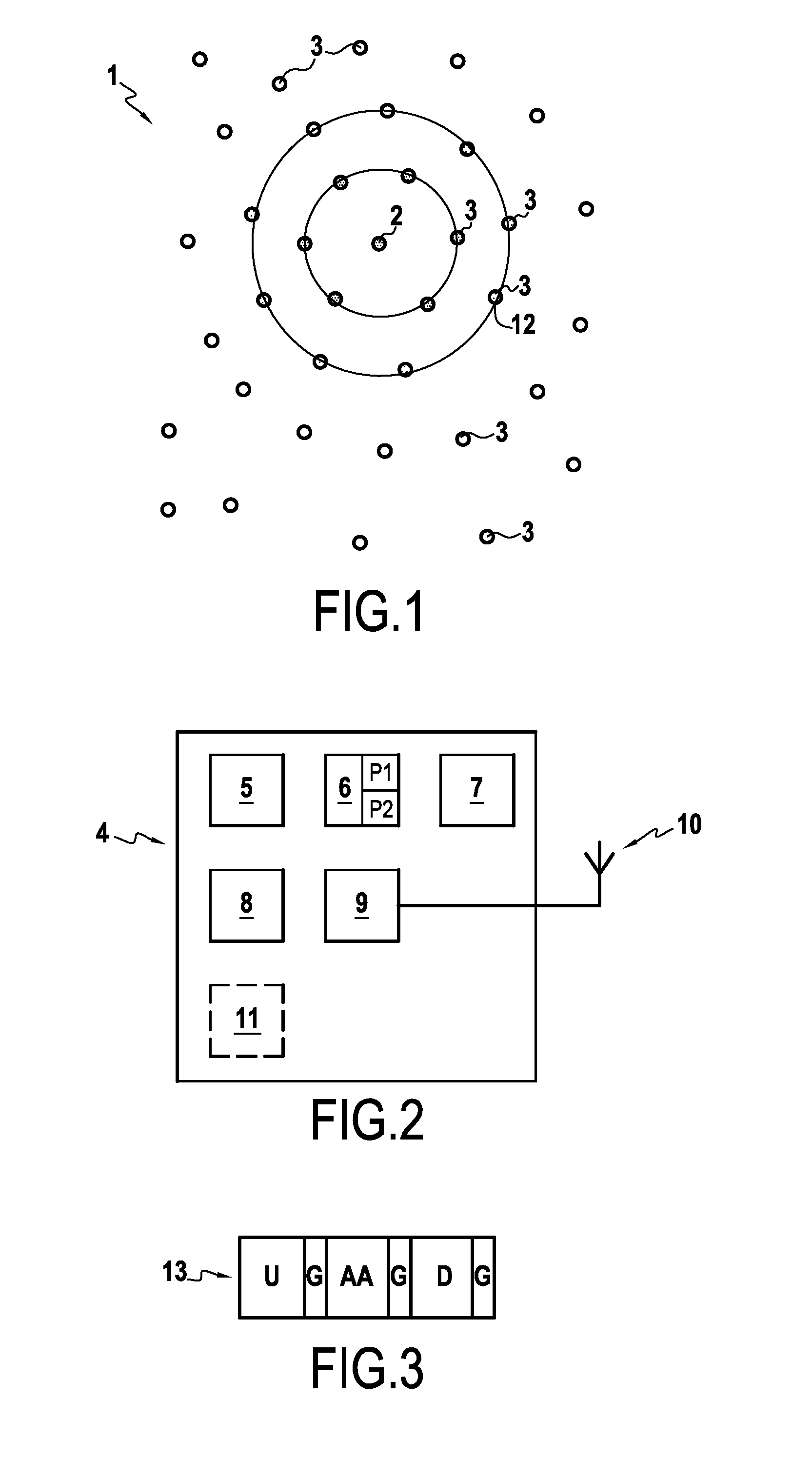
[0082]The invention is described below in the context of a co-operative network made up of nodes and a target entity, in which the nodes are capable of co-operating for transmitting data towards the target entity. By way of example, it may be a network having mobile or fixed access, in which the nodes are access points and the target is a piece of telecommunications equipment, or a network of sensors in which the nodes are sensors and the target entity collects the data coming from the sensors.

[0083]FIG. 1 shows a co-operative network 1 including a target entity 2 and nodes 3. For reasons of clarity, the reference 3 is not marked on each of the nodes in FIG. 1. The nodes 3 and the target entity 2 are synchronized, i.e. they share common knowledge about time T.

[0084]FIG. 2 shows a communications device 4 that may be the target entity 2 or one of the nodes 3. The communications device 4 presents the hardware architecture of a computer and comprises a processor 5, a ROM 6, a random acc...


PUM


Abstract

A communications method executed by a node of a telecommunications network, the method includes: a training step including determining a “transmission” filter as a function of a received training signal; and a data transmission step of transmitting data to a target node of the network while using the transmission filter as determined during the training step.

Description

BACKGROUND OF THE INVENTION[0001]The invention relates to the general field of telecommunications. The invention relates in particular to a co-operative radio network.[0002]In a co-operative radio network, a plurality of access points co-operate to transmit data simultaneously to a target over a wireless connection. The techniques used, known as co-operative beamforming, enable the signal to interference-and-noise ratio (SINR) to be increased at the target, and thus make it possible to increase the transmission data rate.[0003]Typically, data transmission comprises a plurality of stages:[0004]a relay stage in which source access points having data for transmission to the target transmit the data to other access points of the network, with the data being stored therein;[0005]a training stage, in which the target transmits a training sequence; each access point estimates the impulse response of the channel between the target and itself from the sequence it has received as deformed by ...

Claims


Application Information

Patent Timeline
IPC IPC(8): H04W24/02
CPCH04W24/02H04L25/0226H04L25/03343
Inventor PHAN HUY, DINH THUYLEGOUABLE, RODOLPHE
Owner ORANGE SA (FR)
Why Eureka
Try Eureka