

Distributed Architecture for Encoding and Delivering Video Content
a technology of video content and distribution architecture, which is applied in the direction of selective content distribution, color television with bandwidth reduction, television systems, etc., can solve the problems of limited and expensive memory storage, data in a wireless network is transmitted through rf spectrum, and the cost of download traffic becomes a problem for cdn operators and/or media providers, etc., to achieve high quality, great economic benefits, and high definition
- Summary
- Abstract
- Description
- Claims
- Application Information
AI Technical Summary
Benefits of technology
Problems solved by technology
Method used
Image

Examples
Embodiment Construction
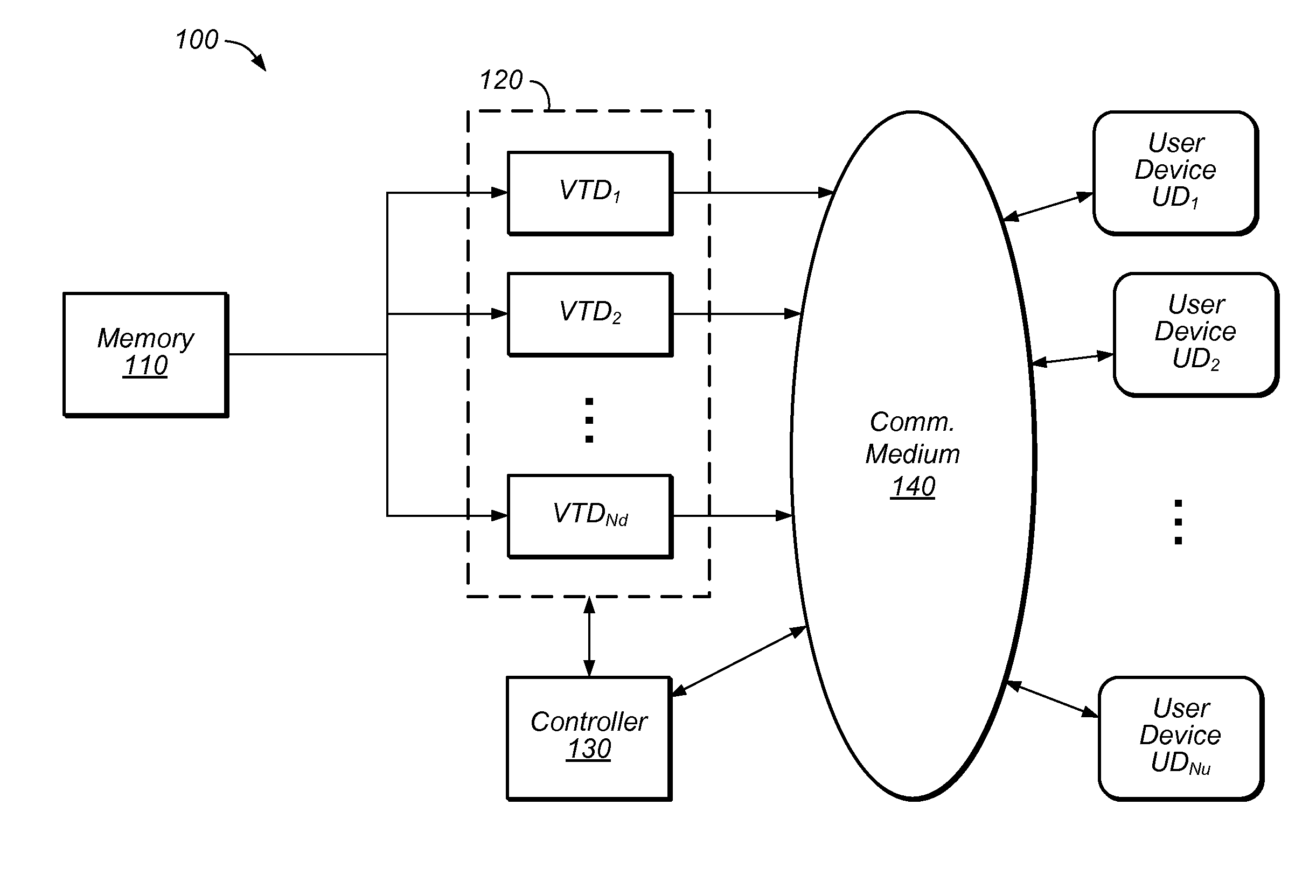
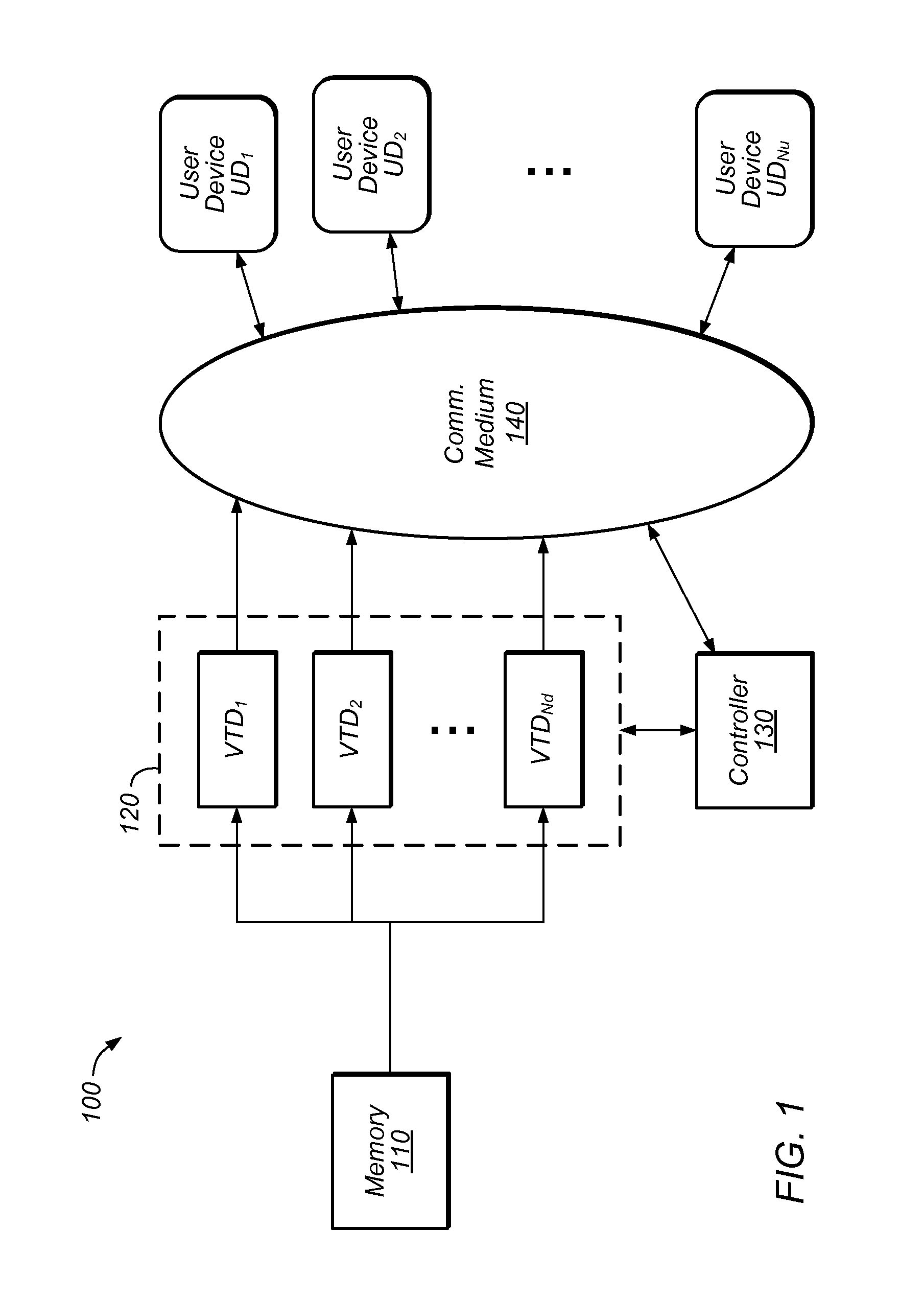
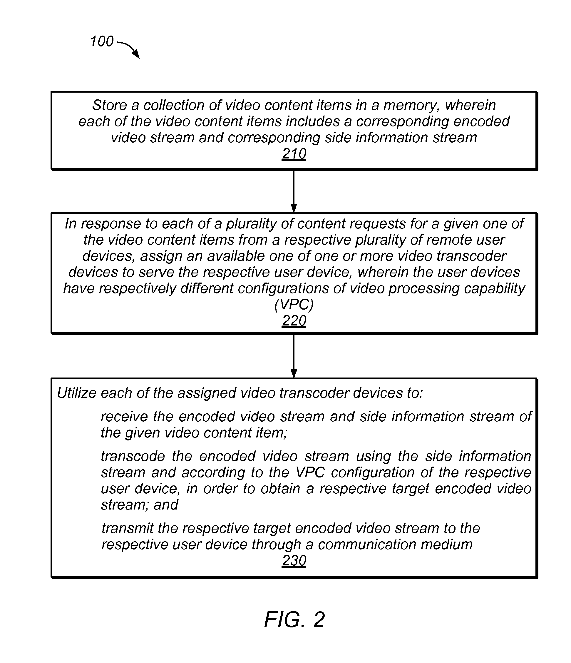
[0002]The present invention relates generally to video content compression and distribution, and in particular, to a split architecture for encoding video content and a rate control mechanism to be used in the split architecture.
DESCRIPTION OF THE RELATED ART
[0003]The demand for video streaming services is ubiquitous and increasing. Thus, there is an ever-increasing need for methods capable of compressing video content and efficiently delivering the video content to user devices through wired and / or wireless networks.
[0004]For example, there is a great demand for the delivery of streaming video service to user devices (e.g., mobile devices) in a wireless network. However, the air interface between the base station (of the wireless network) and the mobile device is vulnerable to radio interference, and the quality of RF propagation changes dynamically due to the movement of objects in the environment, the movement of the mobile device, radio traffic loading and congestion, etc., thus...
PUM
 Abstract
Description
Claims
Application Information