Photoacoustic Measurement Device

a technology of photoacoustic measurement and measurement device, which is applied in the field of photoacoustic measurement method and, can solve the problem that the image with high sensitivity cannot be easily performed in a deep part, and achieve the effect of high sensitivity and high resolution

Inactive Publication Date: 2014-01-02
HITACHI LTD
View PDF4 Cites 11 Cited by
  • Summary
  • Abstract
  • Description
  • Claims
  • Application Information

AI Technical Summary

Benefits of technology

[0019]According to the invention, it is possible to perform photoacoustic imaging in the deep part with high sensitivity and high resolution.

Problems solved by technology

However, while the photoacoustic imaging is influenced by light scattering corresponding to only a half of light scattering of optical imaging, there is still a problem that imaging with high sensitivity is not easily performed in a deep part.

Method used


Image

  • Photoacoustic Measurement Device
  • Photoacoustic Measurement Device
  • Photoacoustic Measurement Device

Examples


Embodiment Construction

[0030]Hereinafter, an embodiment of the invention will be described.

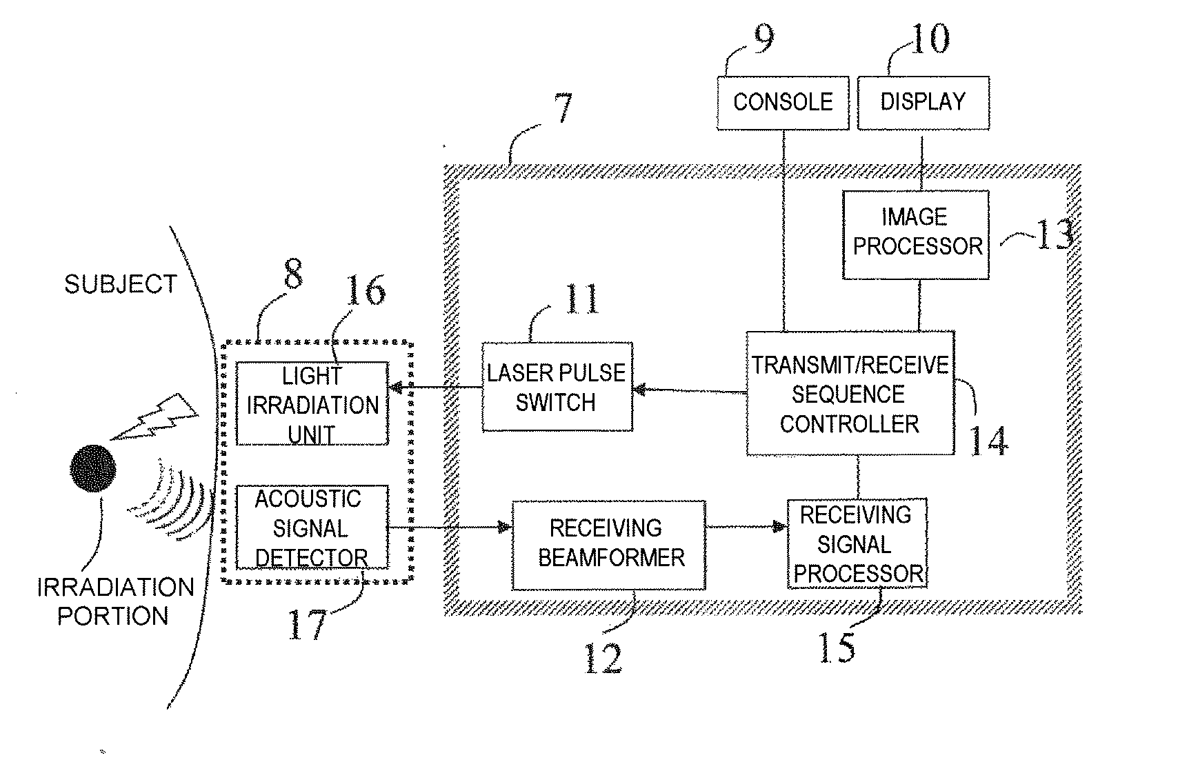
[0031]First, a configuration of a device according to the invention will be described. In a photoacoustic measurement device shown in FIG. 5, a subject to which a photoacoustic contrast agent is administered is irradiated with a laser pulse to obtain an image of the subject from the obtained acoustic signal. To the subject shown in FIG. 5, a photoacoustic contrast agent is administered and the contrast agent will be described after the description of the configuration of the device.

[0032]As shown in FIG. 5, a probe 8, a console 9 and a display 10 are connected to a photoacoustic measurement device main body 7, and further, the photoacoustic measurement device main body 7 includes a laser pulse switch 11, a receiving beamformer 12, an image processor 13, a transmit / receive sequence controller 14 and a receiving signal processor 15.

[0033]The probe 8 is a device which transmits a laser pulse to the subject and receives...


PUM


Abstract

A device and an agent for performing imaging in a deep part with high sensitivity and high resolution are to be provided. A photoacoustic measurement device (photoacoustic imaging device) performs light irradiation on an inspection area of a subject to which a photoacoustic agent generating an acoustic signal by causing phase change from a solid phase or a liquid phase to a gas phase by the light irradiation is administered, while the irradiated energy amount is increased, and detects the acoustic signal generated in the inspection area due to the light irradiation to form an imaged image of the inspection area based on the detected acoustic signal.

Description

TECHNICAL FIELD[0001]The present invention relates to a photoacoustic measurement method and device which visualize information on a subject to which a photoacoustic agent is administered and the like using the photoacoustic agent that generates a characteristic acoustic signal by light irradiation and a photoacoustic measurement device that can distinguish an acoustic signal. Particularly, information on a deep part of a subject using a photoacoustic agent is visualized in detail.BACKGROUND ART[0002]When a material is irradiated with optical energy, a phenomenon that a material absorbs the light energy to cause heat generation and thermal expansion, and then, a thermoelastic wave is generated, is referred to as a photoacoustic effect, and the phenomenon has been widely applied to a spectroscopic analysis and in vivo tomography.[0003]For example, when soft tissue in vivo is irradiated with a laser pulse of about several nanoseconds with a wavelength of visible light to infrared ligh...

Claims


Application Information

Patent Timeline
Patent Type & Authority Applications(United States)
IPC IPC(8): A61B5/00A61B8/14
CPCA61B5/0095A61B8/14A61K49/225A61K49/226G01N21/1702
Inventor ASAMI, REIKAWABATA, KENNICHITAKANO, SHINTAAZUMA, TAKASHI
Owner HITACHI LTD
Why Eureka
Try Eureka