
Control of a brushless motor

a brushless motor and control technology, applied in the direction of motor/generator/converter stopper, dynamo-electric converter control, instruments, etc., can solve the problems of increasing affecting the efficiency of the motor, etc., to achieve the effect of reducing the movement of the rotor during heating, reducing the damage to the motor components, and reducing the cost of the motor

Active Publication Date: 2014-01-09
DYSON TECH LTD
View PDF19 Cites 2 Cited by
  • Summary
  • Abstract
  • Description
  • Claims
  • Application Information

AI Technical Summary

Benefits of technology

The patent describes a way to prevent damage to motor components caused by high speeds and power losses during operation. This is achieved by sequentially energizing and de-energizing the motor's phase winding, followed by a lower current limit at lower temperatures. This reduces damage to the motor and allows it to operate at lower speeds. In addition, the patent also suggests using a switch to create multiple heat sources during each drive period, resulting in better balanced and quicker heating of the motor. The technical effect is improved motor protection and better motor performance.

Problems solved by technology

However, attempting to drive the motor at relatively low temperatures may damage components of the motor.
However, the provision of a heating device increases the cost of the motor.

Method used


Image

  • Control of a brushless motor
  • Control of a brushless motor
  • Control of a brushless motor

Examples


Embodiment Construction

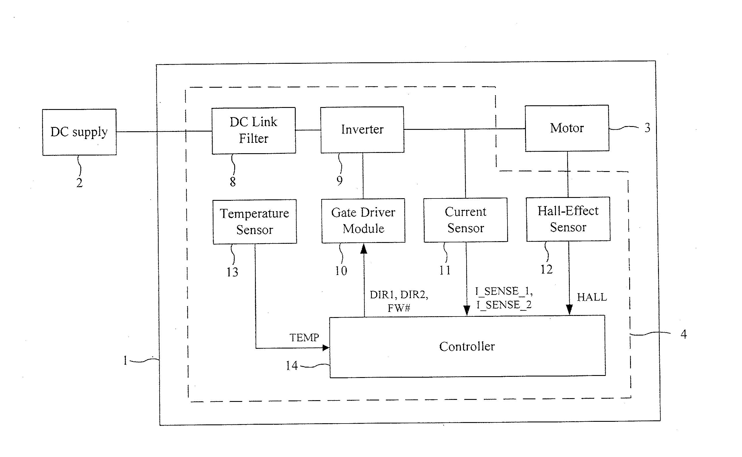
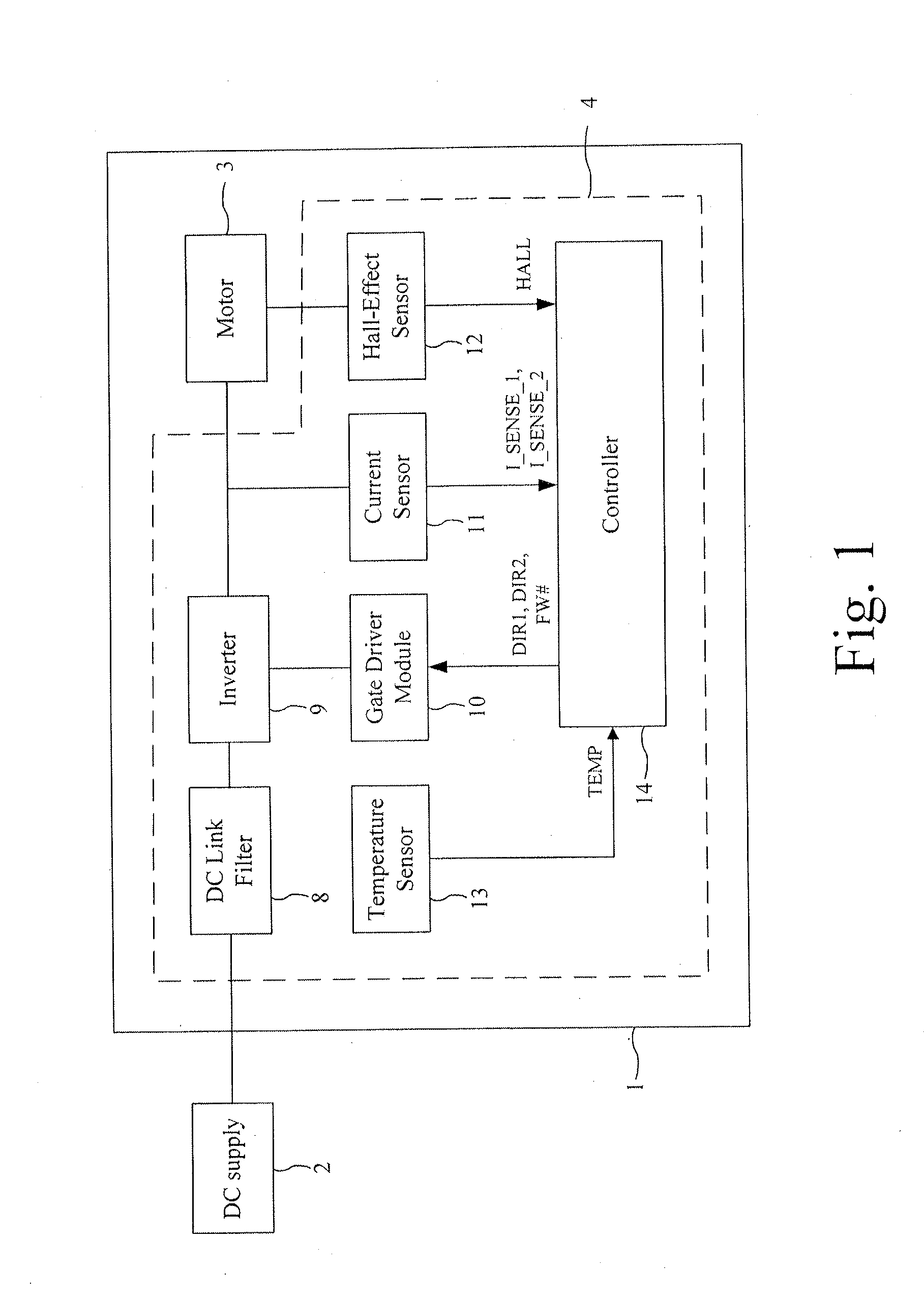
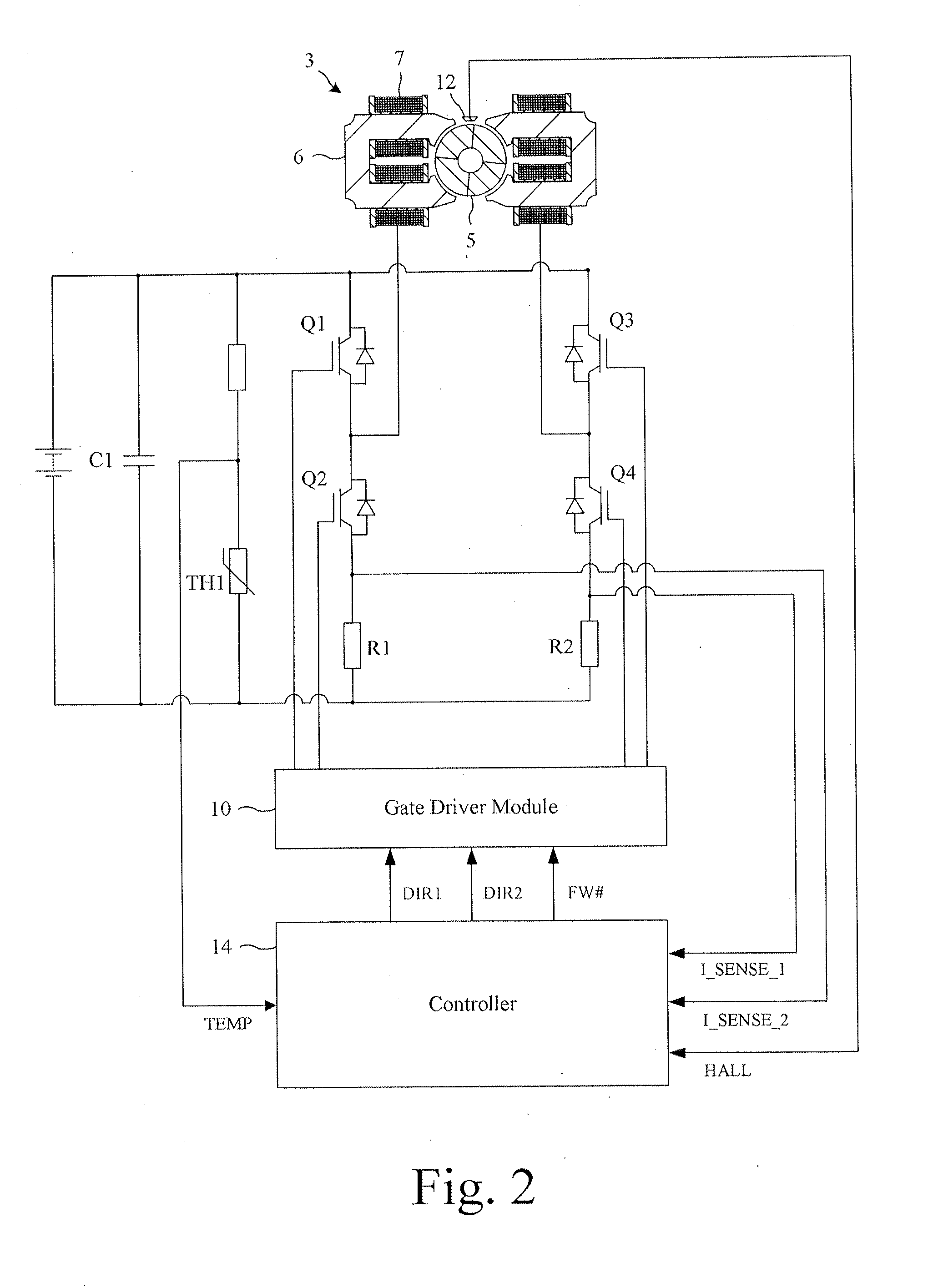
[0026]The motor system 1 of FIGS. 1 and 2 is powered by a DC power supply 2 and comprises a brushless motor 3 and a control system 4.

[0027]The motor 3 comprises a four-pole permanent-magnet rotor 5 that rotates relative to a four-pole stator 6. Conductive wires are wound about the stator 6 and are coupled together (e.g. in series or parallel) to form a single phase winding 7.

[0028]The control system 4 comprises a DC link filter 8, an inverter 9, a gate driver module 10, a current sensor 11, a Hall-effect sensor 12, a temperature sensor 13, and a controller 14.

[0029]The DC link filter 8 comprises a capacitor C1 that smoothes the relatively high-frequency ripple that arises from switching of the inverter 9.

[0030]The inverter 9 comprises a full bridge of four power switches Q1-Q4 that couple the DC link voltage to the phase winding 7. Each of the switches Q1-Q4 includes a freewheel diode.

[0031]The gate driver module 10 drives the opening and closing of the switches Q1-Q4 in response to...


PUM


Abstract

A method of controlling a brushless motor that includes sensing a temperature and using the sensed temperature to define a current limit. A lower current limit is then defined for a lower sensed temperature. A winding of the motor is sequentially energised and de-energised, with the winding being de-energised when current in the winding exceeds the defined current limit.

Description

REFERENCE TO RELATED APPLICATIONS[0001]This application claims the priority of United Kingdom Application No. 1211755.2, filed Jul. 3, 2012, the entire contents of which are incorporated herein by reference.FIELD OF THE INVENTION[0002]The present invention relates to control of a brushless motor.BACKGROUND OF THE INVENTION[0003]It may be necessary to start a brushless motor at temperatures well below that of the normal running temperature. However, attempting to drive the motor at relatively low temperatures may damage components of the motor.[0004]Schemes for preheating a motor are known but generally suffer from one or more disadvantages. For example, the motor may include a heating device that heats the motor to a predetermined temperature prior to starting. However, the provision of a heating device increases the cost of the motor.SUMMARY OF THE INVENTION[0005]The present invention provides a method of controlling a brushless motor, the method comprising sensing a temperature, u...

Claims


Application Information

Patent Timeline
Patent Type & Authority Applications(United States)
IPC IPC(8): H02P1/04
CPCH02P1/04H02P31/00H02P29/032H02P29/62H02P29/64H02P6/26H02P29/66H02P29/662H02P1/465H02P6/20
Inventor GREETHAM, STEPHENHAWKER, DAVID JOHN
Owner DYSON TECH LTD
Learn More