Elastography method, and magnetic resonance system for implementing an elastography method

a technology applied in the field of elastography and magnetic resonance systems, can solve the problems of incompatibility of devices for generation with the environment, inconvenient use of specially designed and expensive equipment, and inability to meet the requirements of the environment, etc., and achieve the effect of simple and cost-effective elastography and high precision

Active Publication Date: 2014-01-09
SIEMENS HEALTHCARE GMBH
View PDF1 Cites 2 Cited by
  • Summary
  • Abstract
  • Description
  • Claims
  • Application Information

AI Technical Summary

Benefits of technology

[0013]Therefore, a need exists for improved elastography techniques. In particular, a need exists for improved elastography techniques using a magnetic resonance system that allow a high precision in the determination of a variable describing tissue elasticity and for techniques that enable simpler and more cost-effective elastography.

Problems solved by technology

In general, these devices for generation are not compatible (or are compatible only to a limited extent) with the environment within an MR system.
Susceptibility artifacts can arise in the MR signals that are generated in the presence of such devices, or specially designed and thus expensive equipment must be used that is more MR-compatible.
Special solutions are then required that complicate the clinical workflow and produce further limitations with regard to the space available to the patient within the magnetic resonance tube.
Moreover, the additional components that are necessary produce increased costs in implementation, as well as increased costs for procurement and servicing.
Space problems also can arise due to the use of mechanical vibration devices or ultrasound emitters.
Since the mechanical vibration devices or ultrasound emitters are most advantageously placed at such locations, the space problems can result.
The use of low-frequency shear waves (for example below 35 Hz, which corresponds to a wavelength of 6 to 17 cm), however, significantly reduces the achievable spatial resolution.
For example, this can hinder or make impossible the detection of smaller tumors, or generally limit the diagnosis evaluation capability.
This can complicate the clinical interpretation of the MRE images or make it impossible.

Method used


Image

  • Elastography method, and magnetic resonance system for implementing an elastography method
  • Elastography method, and magnetic resonance system for implementing an elastography method
  • Elastography method, and magnetic resonance system for implementing an elastography method

Examples


Embodiment Construction

[0060]The present invention is explained in detail in the following using preferred embodiments with reference to the drawings. In the figures, identical reference characters designate identical or similar elements.

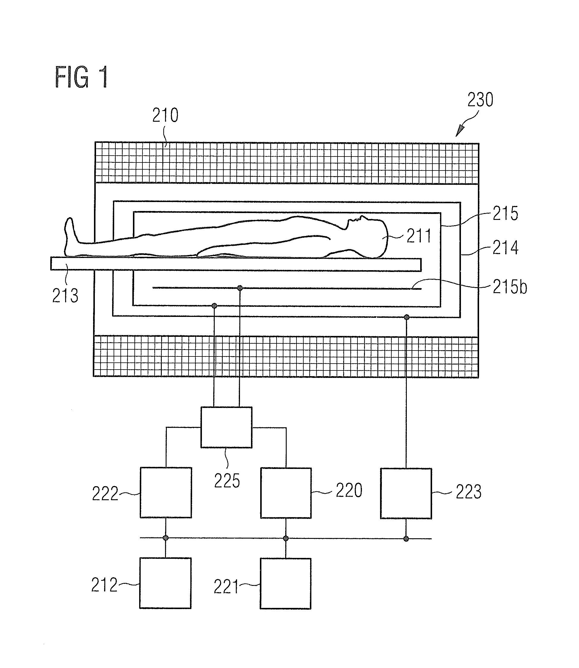
[0061]FIG. 1 schematically shows a magnetic resonance (MR) system 230 according to an embodiment of the present invention. The MR system 230 has a magnet 210 to generate a basic magnetic field. For example, the magnet 210 can be a tube magnet and the basic magnetic field can be situated parallel to the longitudinal axis of the tube. An examination subject—here an examined person 211—can be slid on a bed table 213 into the magnet 210. The MR system 230 furthermore has a gradient system 214 to generate magnetic field gradients that are used for imaging and for spatial coding of detected MR signals. The gradient system 214 typically comprises at least three separately controllable coils or coil sets which enable gradient fields to be applied and switched along defined spatia...


PUM


Abstract

In a methods for elastography in a defined region of an examined person, a radio-frequency pulse is radiated to manipulate a transverse magnetization in the defined region and at least one additional radio-frequency pulse with a spatial selectivity of the amplitude is radiated to generate shear waves in the defined region. A magnetic resonance signal from the defined region is detected and a determination of a value describing the tissue elasticity in the defined region is made based on the magnetic resonance signal.

Description

BACKGROUND OF THE INVENTION[0001]1. Field of the Invention[0002]The present invention concerns techniques for elastography and a magnetic resonance system for implementing those techniques. More particularly, the invention concerns techniques of elastography in which shear waves are generated by a radio-frequency coil array of such a magnetic resonance system.[0003]2. Description of the Prior Art[0004]Elastography is a medical examination modality that allows a determination of tissue elasticity to be made. For example, magnetic resonance elastography (MRE) is a known technique that allows properties of shear waves (transverse sound waves in a frequency range of approximately 10-200 Hz) within body tissue to be detected and imaged by means of magnetic resonance signals. The shear waves are applied or generated on the outer surface of the body, for example by a mechanical vibration device. Their propagation is monitored within the body tissue by means of magnetic resonance signals th...

Claims


Application Information

Patent Timeline
Patent Type & Authority Applications(United States)
IPC IPC(8): A61B5/055
CPCA61B5/055A61B5/02007A61B8/485G01R33/56358
Inventor POPESCU, STEFAN
Owner SIEMENS HEALTHCARE GMBH
Why Eureka
Try Eureka