
Optically heated analyte desorber for gas chromatography analysis

an analyte desorber and gas chromatography technology, which is applied in the direction of chemistry apparatus and processes, instruments, etc., can solve the problems of slow and inefficient desorption process, thermal degradation and rearrangement of analytes, and decrease the uniformity of analyte retrieval, so as to reduce re-adsorption, improve quantitative results, and accelerate the desorption of analytes

Inactive Publication Date: 2014-01-30
BAE SYST INFORMATION & ELECTRONICS SYST INTERGRATION INC
View PDF16 Cites 10 Cited by
  • Summary
  • Abstract
  • Description
  • Claims
  • Application Information

AI Technical Summary

Benefits of technology

The invention is a new method and device that allows for quick and efficient heating of a carbonaceous powder sample to desorb analytes while reducing thermal degradation and rearrangement of the analytes. This is achieved by distributing the sample onto a surface and irradiating it with a heating light source. The carbon absorbs the light energy, resulting in a very rapid heating of the particle skin to a depth of several microns. This intense surface heating causes a quick and efficient thermal desorption, without overheating and therefore with reduced thermal degradation and reduced rearrangement of the analyte molecules before their release from the carbon surface.

Problems solved by technology

This indirect heating desorption process can be slow and inefficient, and attempts to speed up the process by applying more heat may lead to thermal degradation and rearrangement of the analytes.
Also, desorption utilizing indirect thermal conduction heating can decrease the uniformity of the analyte retrieval, thereby leading to inaccurate quantitative analysis, especially when applied to a carbonaceous sorbent material that has poor heat conductivity, and particularly for large, high boiling point analytes.
This geometry greatly compounds the difficulty of obtaining quantitative results.

Method used


Image

  • Optically heated analyte desorber for gas chromatography analysis
  • Optically heated analyte desorber for gas chromatography analysis
  • Optically heated analyte desorber for gas chromatography analysis

Examples


Embodiment Construction

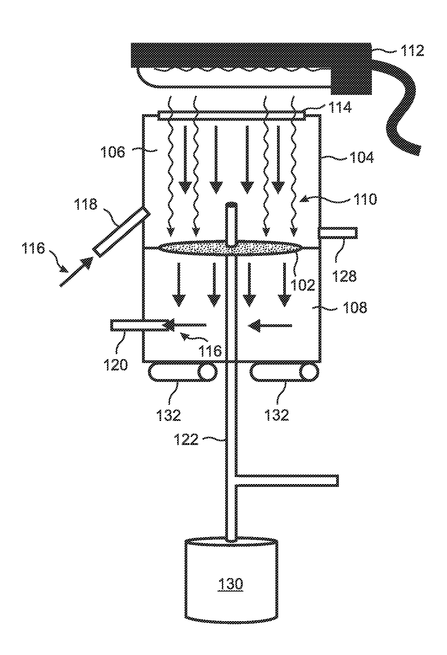
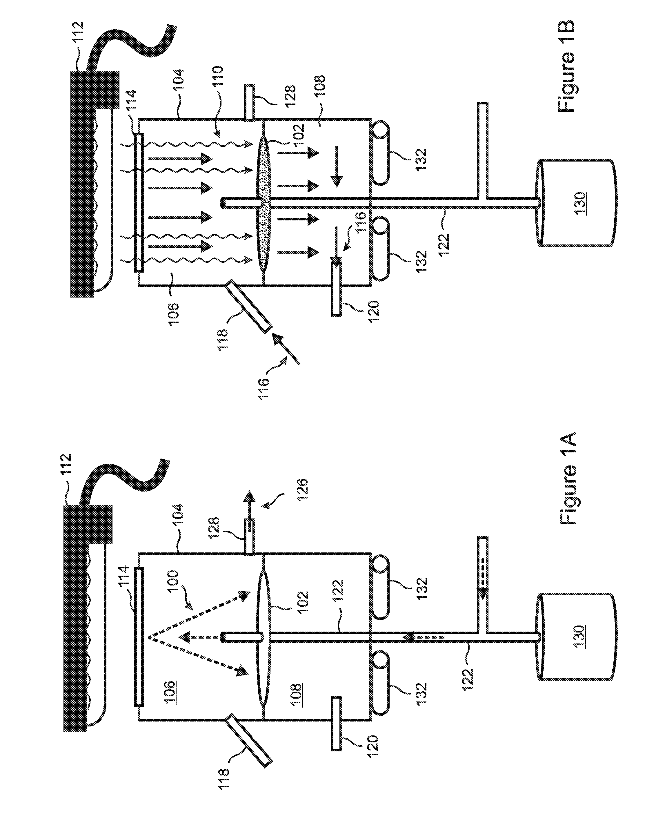
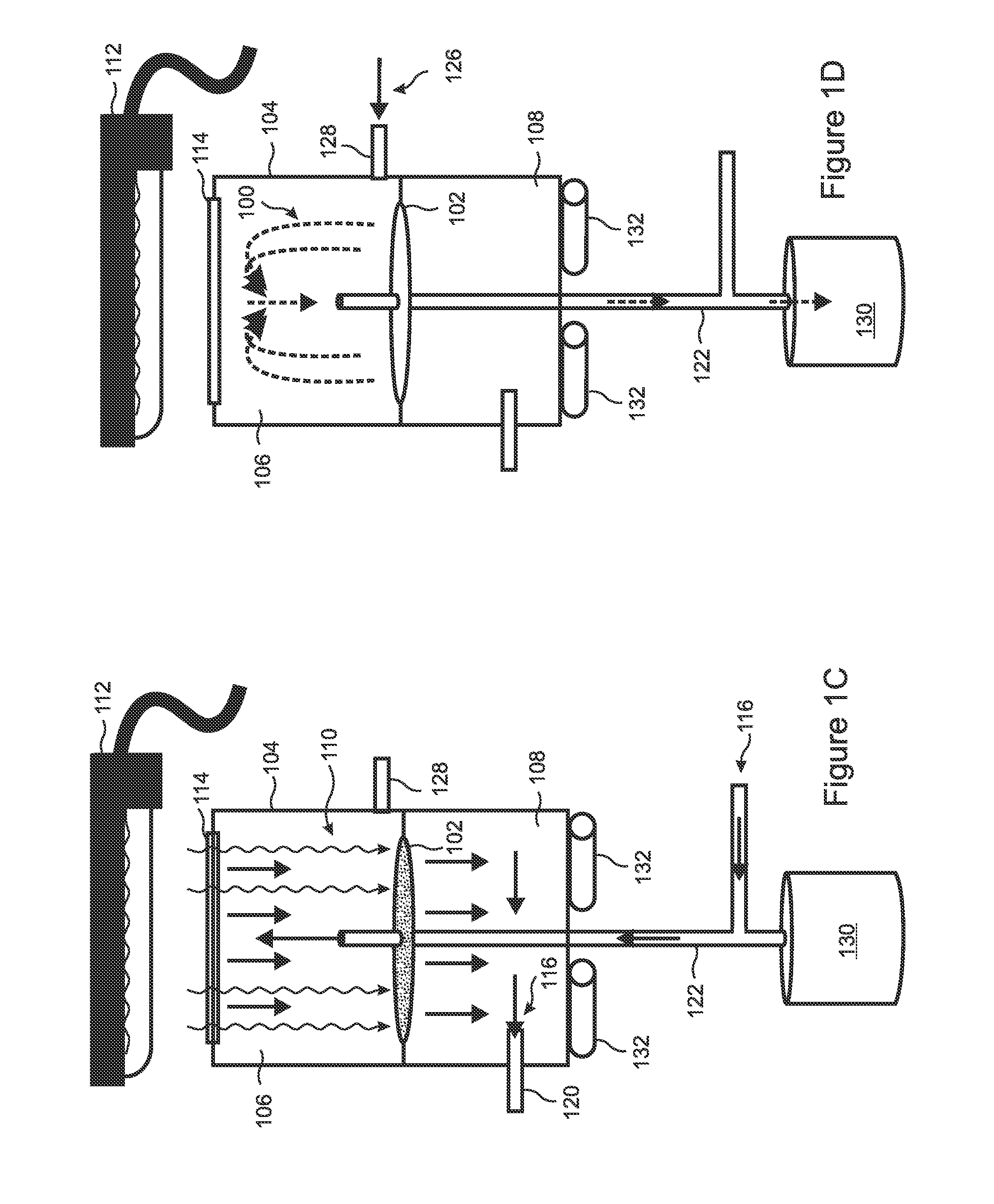
[0043]The present invention is a novel apparatus and method for providing rapid desorption of analytes from a carbonaceous sorbent powder sample with reduced re-adsorption and correspondingly improved quantitative results, and with reduced thermal degradation and rearrangement of the adsorbed analytes. According to the invention, the entire sorbent powder sample is simultaneously and uniformly heated in a rapid, efficient, manner by distributing the sample onto a desorbing surface within an enclosed chamber in a uniformly thin layer, and directly irradiating the sample with a heating light source. In embodiments, the thin layer is approximately one powder granule in thickness, so that substantially all of the powder granules are heated simultaneously.

[0044]Because the carbonaceous sorbent is a strong black body light absorber, direct adsorption of light energy from illumination of the sorbent powder causes a very rapid and intense heating of the particle skin to a depth of several m...


PUM

PropertyMeasurementUnit
flow rateaaaaaaaaaa
pressureaaaaaaaaaa
temperatureaaaaaaaaaa

Abstract

Analytes are rapidly desorbed from a carbonaceous sorbent powder with improved quantitation and reduced analyte re-adsorption, thermal degradation, and rearrangement. The sample is distributed in a thin layer onto a desorption surface within a chamber. The layer can be a monolayer. Heating light irradiates the sample through a window, directly and rapidly heating the sample while the desorbed analytes diffuse into a vacuum or are removed by a carrier gas. Finally, the sorbent is flushed from the chamber by a transport gas. The desorption surface can be an inner surface of the window, or a surface of a porous frit that divides the chamber into two sections. The frit can be stainless steel or glass. The carrier gas can be helium, argon, or carbon dioxide. The light source can be a tungsten halogen lamp. A heater can control the chamber temperature according to a heating profile.

Description

RELATED APPLICATIONS[0001]This application claims the benefit of U.S. Provisional Applications No. 61 / 508,809, filed Jul. 18, 2011 which is herein incorporated by reference in its entirety for all purposes.STATEMENT OF GOVERNMENT INTEREST[0002]The invention was made with United States Government assistance under contract no. HR0011-08-C-0056 awarded by the Defense Advanced Research Projects Agency (DARPA). The United States Government has certain rights in the invention.FIELD OF THE INVENTION[0003]The invention relates to apparatus and methods for desorption of analytes from sorbent materials for gas chromatography analysis, and more particularly, to heat-induced desorption of analytes adsorbed on carbonaceous sorbent materials.BACKGROUND OF THE INVENTION[0004]A common method of collecting a sample for analysis by gas chromatography is “solid phase micro-extraction,” or SPME. In this method, a sorbent material is exposed to an environment containing analytes, causing some of the ana...

Claims


Application Information

Patent Timeline
Patent Type & Authority Applications(United States)
IPC IPC(8): B01J20/281
CPCG01N30/482B01J20/3416B01J20/3441G01N30/06G01N1/4022G01N1/405G01N2030/122B01J20/20
Inventor BOWERS, II, MICHAEL J.KIPPENY, TADD C.
Owner BAE SYST INFORMATION & ELECTRONICS SYST INTERGRATION INC
Learn More