
Method for preparing porous carbon nanofibers containing a metal oxide, porous carbon nanofibers prepared using the method, and carbon nanofiber products including same

a technology of porous carbon nanofibers and carbon nanofibers, which is applied in the field of carbon nanofibers, can solve the problems of limited capacity and reaction rate, difficult to reproduce adsorption and desorption rate, and difficult to use activated carbon fibers as energy storage media, etc., and achieves fast adsorption and desorption, easy control, and increased energy density.

Inactive Publication Date: 2013-01-31
IND FOUND OF CHONNAM NAT UNIV
View PDF4 Cites 11 Cited by
  • Summary
  • Abstract
  • Description
  • Claims
  • Application Information

AI Technical Summary

Benefits of technology

The present patent text describes a method of making carbon nanofibers with a high specific surface area and improved electrical conductivity. This is achieved by adding a metal alkoxide to a carbon nanofiber precursor solution and performing a carbonization or activation process. The resulting carbon nanofibers have a large specific surface area and can be used in various products.

Problems solved by technology

Among highly functional carbon materials, activated carbon has a high specific surface area, but the pore structure thereof is very complex, making it difficult to reproduce adsorption and desorption rates.
In the case of activated carbon fibers, the fine pores are exposed to the outside, but have a diameter on the micrometer scale, and thus exhibit limited capacity and reaction rate, which make it difficult to use the activated carbon fibers as energy storage media.
However, in the carbon nanofiber preparation method including the chemical activation process that employs a salt, there are problems in that it is difficult to carry out the process continuously and to prepare large amounts of porous carbon nanofibers, because heat-treatment is carried out after the uniform mixing of the carbon nanofibers with the salt, and a process of removing the added salt is required after the activation process.
However, the PAN-based carbon fibers have a low specific surface area and low electrical conductivity, and do not sufficiently exhibit the performance of electrodes for double layer supercapacitors.
Meanwhile, the fiber diameter of the pitch-based carbon nanofibers prepared by the above method is disadvantageously very large because the ability to be spun is low.
Generally, aqueous electric double-layer capacitors have a shortcoming in that their operating voltage is as low as 1.0 V or lower and the amount of energy that can be stored therein is limited.
However, when the organic solvent electrolyte is used, there is the disadvantage of increasing the internal resistance of the capacity so that the charge / discharge characteristics are poor compared to those of aqueous double-layer capacitors.
In the case of the latter, the graphite carbon material is heat-treated with an alkaline material (KOH, NaOH or K2CO3) at a high temperature of 700˜900° C., and the activated material has a capacitance of about 30-50 F / mL per electrode volume at 3.5 V. However, it was reported that activated carbon materials prepared by the alkaline activation method have problems in that they should be heat-treated during their preparation, corrode containers, the characteristics thereof are deteriorated due to charge / discharge cycles and the production cost thereof is high.
However, the process used in this preparation method is complex, and the diameter of the fibers is large, making it difficult to effectively increase the specific surface per volume.
Furthermore, when the fibers are used in the form of woven fabric as an electrode, the density of the electrode is low because of the large diameter of the fibers, and thus the high-speed charge / discharge or high-output properties are deteriorated.

Method used

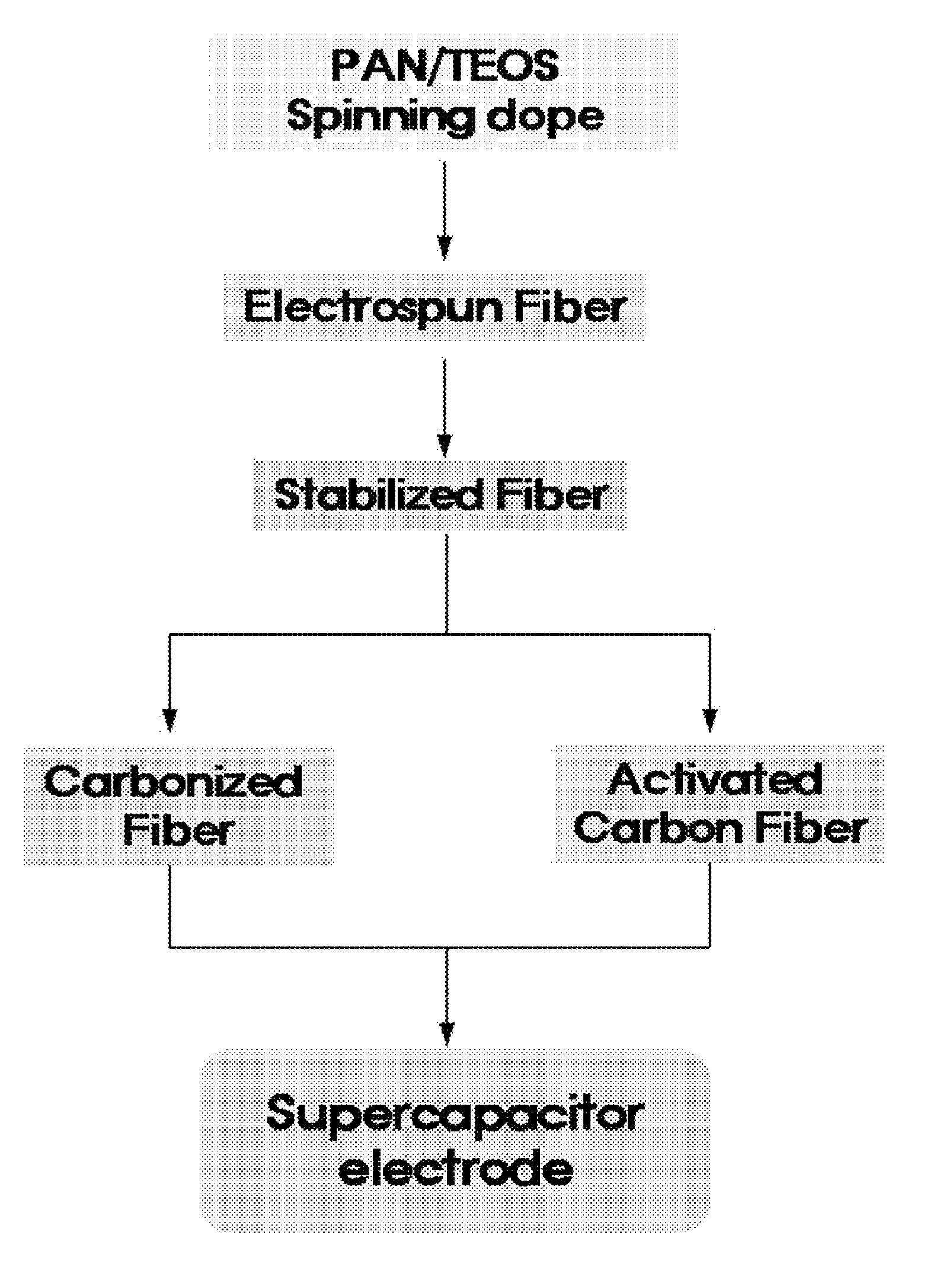
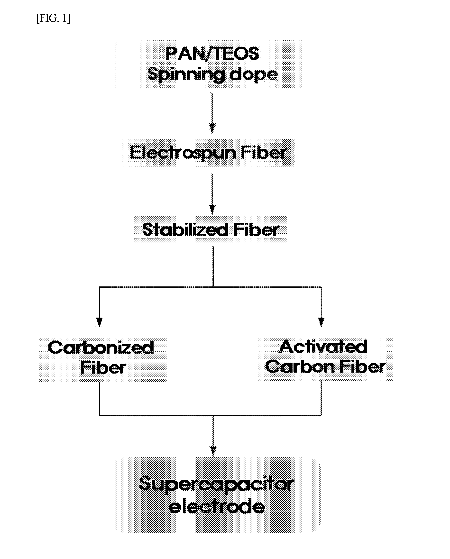
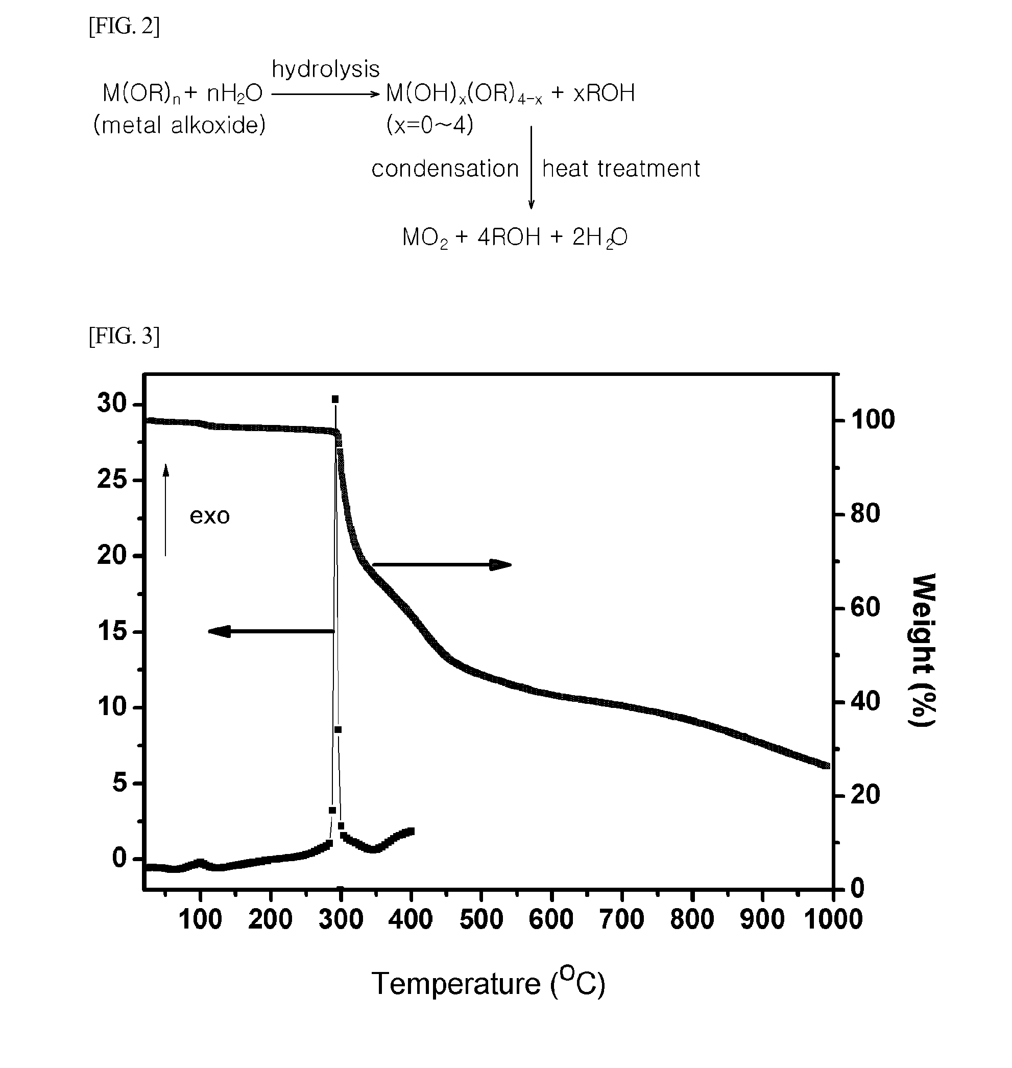

Image

  • Method for preparing porous carbon nanofibers containing a metal oxide, porous carbon nanofibers prepared using the method, and carbon nanofiber products including same
  • Method for preparing porous carbon nanofibers containing a metal oxide, porous carbon nanofibers prepared using the method, and carbon nanofiber products including same
  • Method for preparing porous carbon nanofibers containing a metal oxide, porous carbon nanofibers prepared using the method, and carbon nanofiber products including same

Examples


example 1

[0080]A polyacrylonitrile (PAN) homopolymer as a carbon nanofiber precursor and tetraethyl orthosilicate (Si(OEt)4, TEOS) (Si-alkoxide) as a metal alkoxide [(M(OR)n] were prepared. The prepared PAN and TEOS were dissolved in the solvent DMF, thereby preparing a carbon nanofiber precursor solution. Herein, the carbon nanofiber precursor solution was prepared to have a carbon nanofiber precursor concentration of 10% and to contain PAN and Si-alkoxide at a ratio of 80:20 wt %.

[0081]Then, the prepared carbon nanofiber precursor solution was electrospun to prepare nonwoven fabric webs consisting of nanofibers, thereby obtaining electrospun fibers.

[0082]In the electrospinning process, a voltage of 25 kV was applied to each of the nozzle and collector of the electrospinning apparatus, and the distance between the spinneret and the collector was set at about 20 cm and could be changed if necessary.

[0083]The electrospun fibers resulting from the electrospinning process were stabilized by pla...

example 2

[0084]The stabilized fibers were carbonized by heating the fibers to 800° C. at a rate of 5° C. / min in an inert atmosphere and then maintaining the fibers at that temperature for 50 minutes, thereby preparing porous carbon nanofibers 1.

example 3

[0085]The procedure of Examples 1 and 2 was repeated, except that the carbonization temperature was increased to 900° C., thereby preparing porous carbon nanofibers 2.


PUM

PropertyMeasurementUnit
flow rateaaaaaaaaaa
temperatureaaaaaaaaaa
sizeaaaaaaaaaa

Abstract

The present invention relates to carbon nanofibers, and more particularly, to a method capable of preparing metal oxide-containing porous carbon nanofibers having a high specific surface area by changing the composition of a spinning solution, which is used in a process of preparing carbon nanofiber by electrospinning, and to metal oxide-containing porous carbon nanofibers prepared by the method, and carbon nanofiber products comprising the same.

Description

BACKGROUND[0001]1. Technical Field[0002]The present invention relates to carbon nanofibers, and more particularly, to a method capable of preparing metal oxide-containing porous carbon nanofibers having a high specific surface area by changing the composition of a spinning solution, which is used in a process of preparing carbon nanofiber by electrospinning, and to metal oxide-containing porous carbon nanofibers prepared by the method, and carbon nanofiber products comprising the same.[0003]2. Description of the Related Art[0004]With the advent of the ubiquitous era, the development of environmentally friendly and highly efficient materials is necessary to achieve the miniaturization of various electronic telecommunication devices and the practical use of electric vehicles.[0005]In the 21st century, high-tech small-size mobile power systems are needed and the size and weight of these systems must be reduced. In connection with this requirement, highly functional carbon materials hav...

Claims


Application Information

Patent Timeline
Patent Type & Authority Applications(United States)
IPC IPC(8): H01B1/04B29B9/06H01G9/00D02G3/02D02G3/22B01J20/20D01F9/12
CPCB82Y30/00B82Y40/00D01D5/0007D01D5/247Y10T428/2918H01G11/24H01G11/32H01G11/84Y02E60/13D01F9/22
Inventor YANG, KAP SEUNGKIM, BO HYE
Owner IND FOUND OF CHONNAM NAT UNIV
Learn More