Air-cooled engine surface cooler

a surface cooler and air-cooled technology, applied in the field of turbines, can solve the problems of obstructing air flow, limited space in this region of the engine, and newer engine technologies, which have more heat that must be dissipated, so as to increase the turbulence level of the fluid flowing, promote increased mixing, and reduce the effect of heat transfer

a surface cooler and air-cooled technology, applied in the field of turbines, can solve the problems of obstructing air flow, limited space in this region of the engine, and newer engine technologies, which have more heat that must be dissipated, so as to increase the turbulence level of the fluid flowing, promote increased mixing, and reduce the effect of heat transfer

US20140027102A1Active Publication Date: 2014-01-30GENERAL ELECTRIC CO

Image

  • Air-cooled engine surface cooler
  • Air-cooled engine surface cooler
  • Air-cooled engine surface cooler

Examples


Embodiment Construction

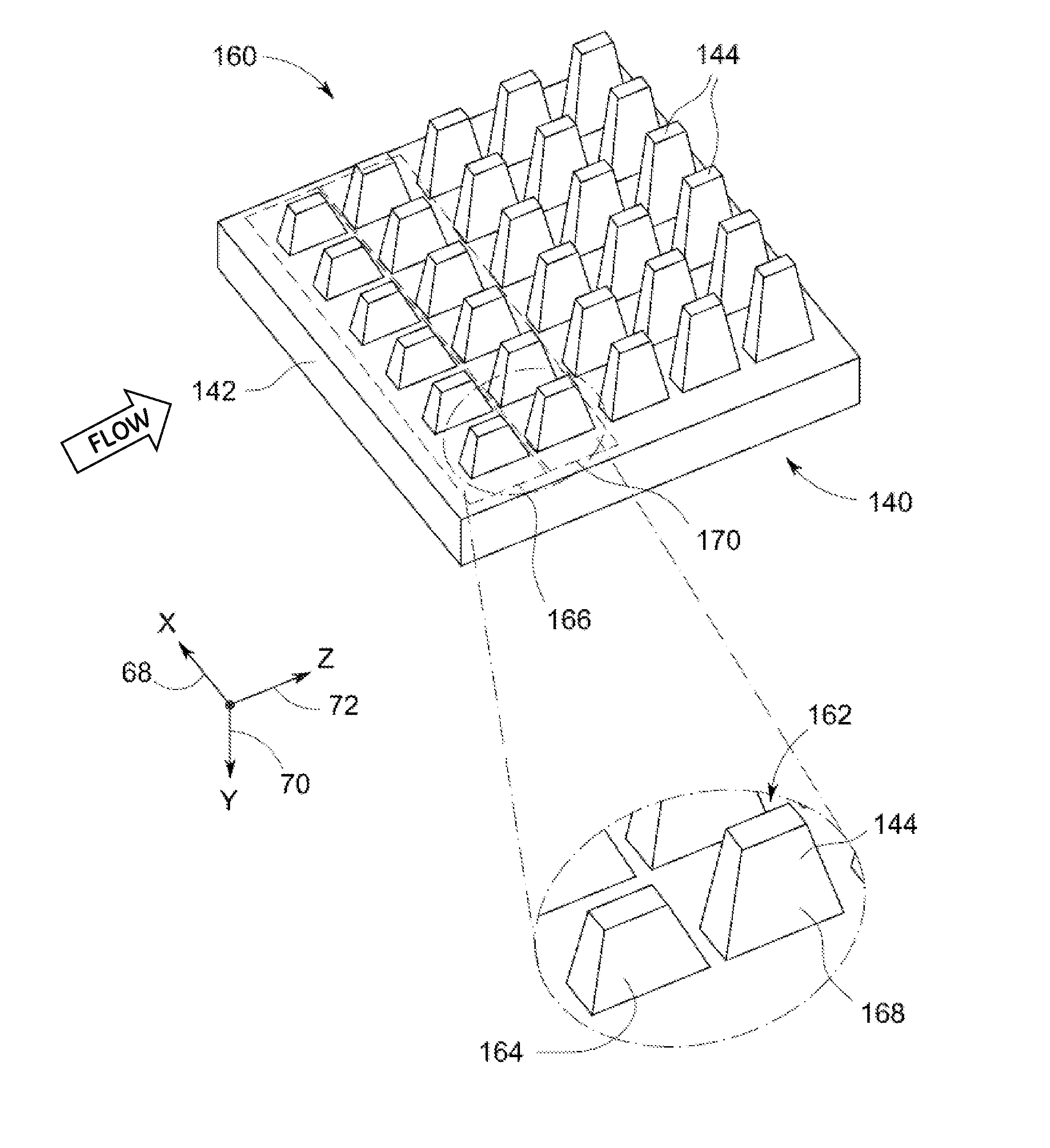
[0024]Embodiment disclosed herein relate to surface coolers and more particularly to enhanced surface coolers for use in a nacelle of an engine such as an aircraft engine. The exemplary surface coolers may be used for providing efficient cooling. Further, the term “surface coolers” as used herein may be used interchangeably with the term “heat exchangers”. As used herein, the surface coolers are applicable to various types of turbomachinery applications such as, but not limited to, turbojets, turbo fans, turbo propulsion engines, aircraft engines, gas turbines, steam turbines, wind turbines, and water turbines. In addition, as used herein, singular forms such as “a”, “an”, and “the” include plural referents unless the context clearly dictates otherwise.

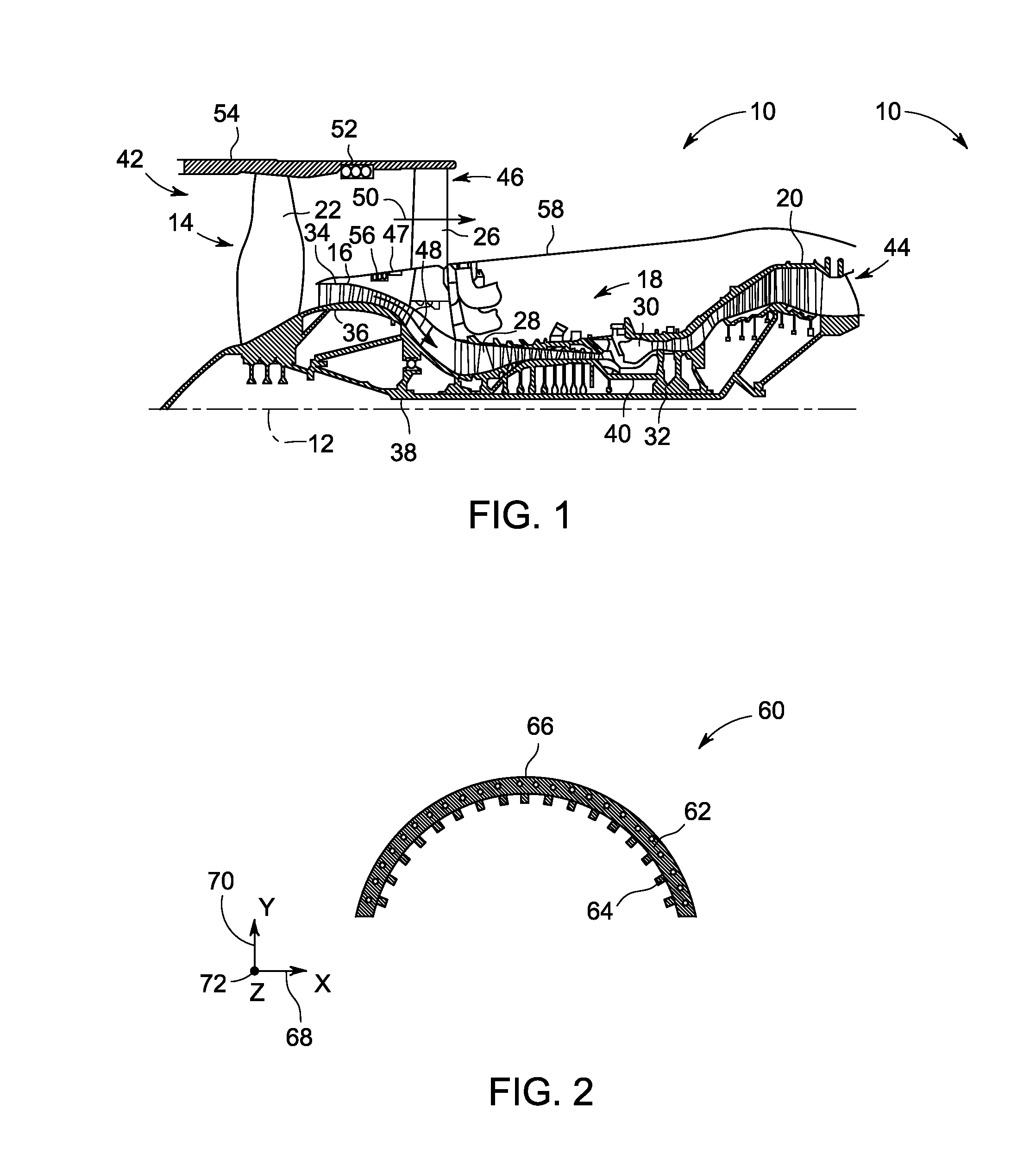
[0025]FIG. 1 is a schematic illustration of an exemplary aircraft engine assembly 10 in accordance with the present disclosure. Reference numeral 12 may be representative of a centerline axis 12. In the exemplary embodiment, the engin...


PUM

PropertyMeasurementUnit
thicknessaaaaaaaaaa
diameteraaaaaaaaaa
thermally conductiveaaaaaaaaaa

Abstract

A surface cooler comprises a plate-like layer and a plurality of spaced-apart fins extending substantially perpendicular from an uppermost layer of the plate-like layer. The plurality of fins defining a plurality of air flow paths. The plurality of spaced-apart fins are configured to augment heat transfer of the surface cooler by increasing the turbulence levels of a fluid flowing through the airflow paths by promoting increased mixing with a resulting increase in the heat transfer coefficient of the surface cooler. A method of forming the surface cooler and an engine including the surface cooler.

Description

BACKGROUND[0001]This invention relates generally to turbomachines, and more particularly to the design of an enhanced heat exchanger, in the form of an air-cooled surface cooler, for use in turbomachines.[0002]Modern turbofan / turbojet engines have an ever-increasing demand of cooling, including gearbox oil, cooling air and electronics, while at the same time their efficiency has to be pushed ever higher. Currently air-cooled oil coolers are usually plate-fin type “brick” heat exchangers that are mounted within the bypass channel to receive flow from the engine intake or bypass stream or from a separate air-intake in the nacelle. New designs have mitigated the high drag of this design due to the plate-fin exchanger sitting in the bypass channel by utilizing a surface cooler that is mounted flush with the aft fan cowling. However, the space in this region of the engine is limited and current designs utilize nearly all the available space. As a result, newer engine technologies, which ...

Claims


Application Information

Patent Timeline
30 Jan 2014
Publication
US20140027102A1
IPC
F28F3/02; B23P15/26
CPC
B23P15/26; F28F3/02; F28D1/0246; F02K3/115; F28F3/048; F28F21/084; F28D1/06; F28F1/16
Inventors
ANTEL, JR., WILLIAM JOSEPH; DIAZ, CARLOS ENRIQUE